Method and apparatus for geometric variations to integrate parametric computer aided design with tolerance analyses and optimization

a computer aided design and geometric variation technology, applied in the field of computer assisted design, can solve the problems of not being able to retrofit a model to the tolerance standard, the modern parametric cad system is limited to nominal geometry and idealized constraints, and the variation is not now well understood by many engineers in design and manufacturing. the effect of investigation

Inactive Publication Date: 2005-11-08
THE ARIZONA BOARD OF REGENTS ON BEHALF OF THE UNIV OF ARIZONA
View PDF8 Cites 103 Cited by
  • Summary
  • Abstract
  • Description
  • Claims
  • Application Information

AI Technical Summary

Benefits of technology

[0027]The invention is a bi-level math model, namely local and global model, which will not only make it easy to investigate which dimensions and features contribute and how to optimally distribute (allocate) the allowable net variation, but also to provide a mechanism for visualizing all types of geometric variations and their combinations. It will also be shown that the method of the invention is compatible with the ANSI / ASME tolerance standard.

Problems solved by technology

These variations are not now well understood by many engineers in design and manufacturing.
However, effective tools for assisting designers in allocating tolerances and identifying trade-offs during the design process do not exist today because of (a) a lack of integration between CAD systems and tolerance analysis software, and (b) the inability of the latter to treat dimensional and geometric tolerances in three dimensions consistently with ASME Y14.5 standard.
Today's modern parametric CAD systems are limited to nominal geometry and idealized constraints; tolerances are supported superficially as textual attributes attached to geometric entities.
The attempt to retrofit a model to the tolerance standard has not gone far enough.
The scope of tolerance analysis is also not adequate to answer many of the designer's queries.
Application to the general three dimensional problem is limited because of (a) difficulty of solving constraint equations in three dimensional, and (b) the equations are written and solved for vertex positions, limiting application to only polyhedral parts.
The construction of such a composite tolerance zone from boundary surfaces of the part does not allow one to model each type of variation separately, nor to study their interactions.
Another problem is that some tolerances in the ASME standard, such as position, apply to axes or mid planes of toleranced features, not the boundary; these cannot be modeled by such offset zones.
This model leads to some topological problems, such as maintenance of tangency and incidence conditions.
However, this representation is unable to distinguish between variation resulting from size, form, and location.
One error built into these systems is that all contributors are considered independent of each other.
Both approaches are based on parametric models, and thus have the limitations given before.
The variational approach can only be used for solving equations in two dimensional, while the procedural approach cannot handle coupled constraints, in general because a step by step construction procedure must be specified to relate the dimension to be analyzed and the contributors.
To the casual observer the capabilities of these systems may be misleading.
Commercial systems have many limitations, particularly the lack of full conformance to the Y14.5 standard.
These problems result from a lack of a fundamental model for geometric variations of imperfect parts.

Method used


Image

  • Method and apparatus for geometric variations to integrate parametric computer aided design with tolerance analyses and optimization
  • Method and apparatus for geometric variations to integrate parametric computer aided design with tolerance analyses and optimization
  • Method and apparatus for geometric variations to integrate parametric computer aided design with tolerance analyses and optimization

Examples


Embodiment Construction

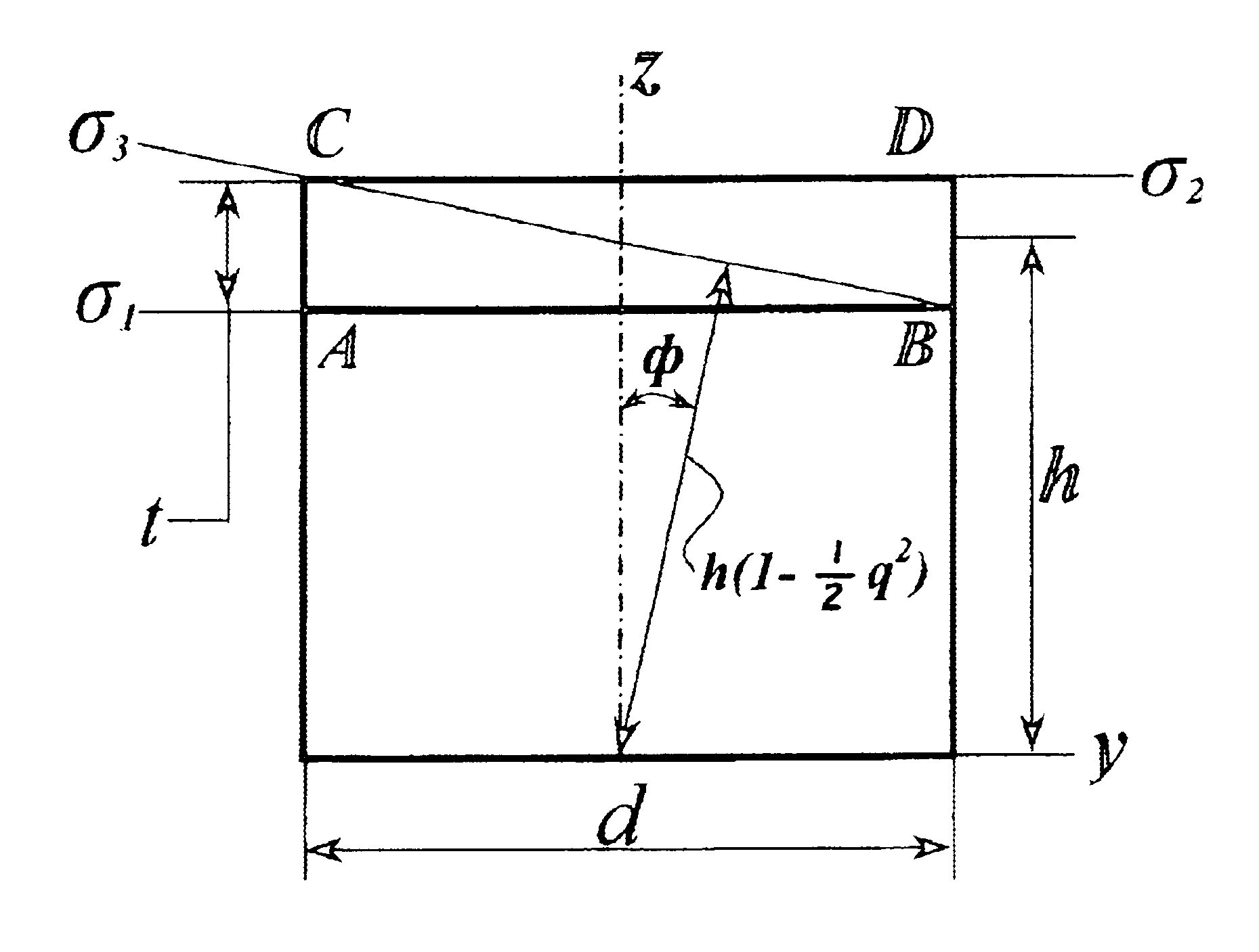
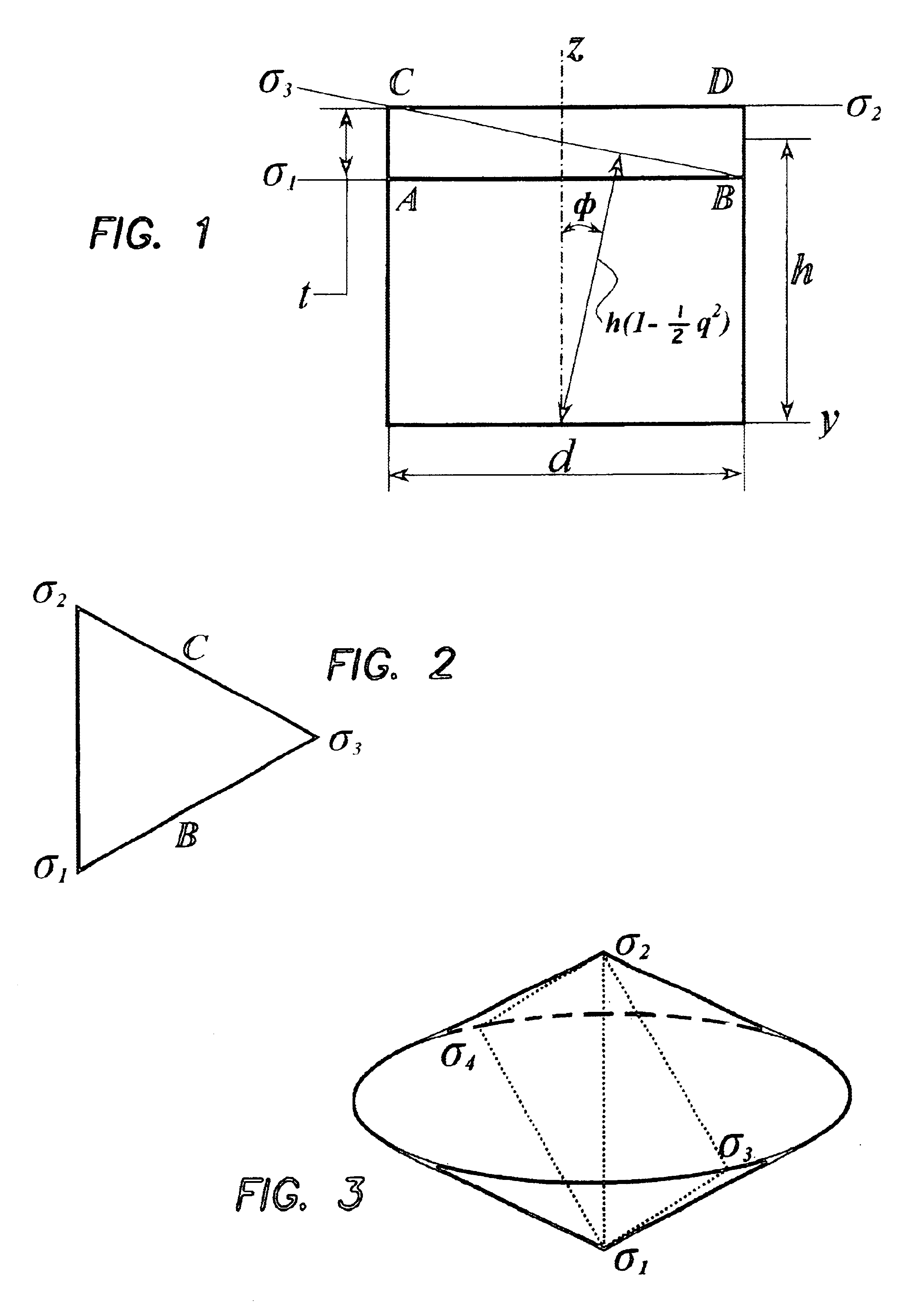
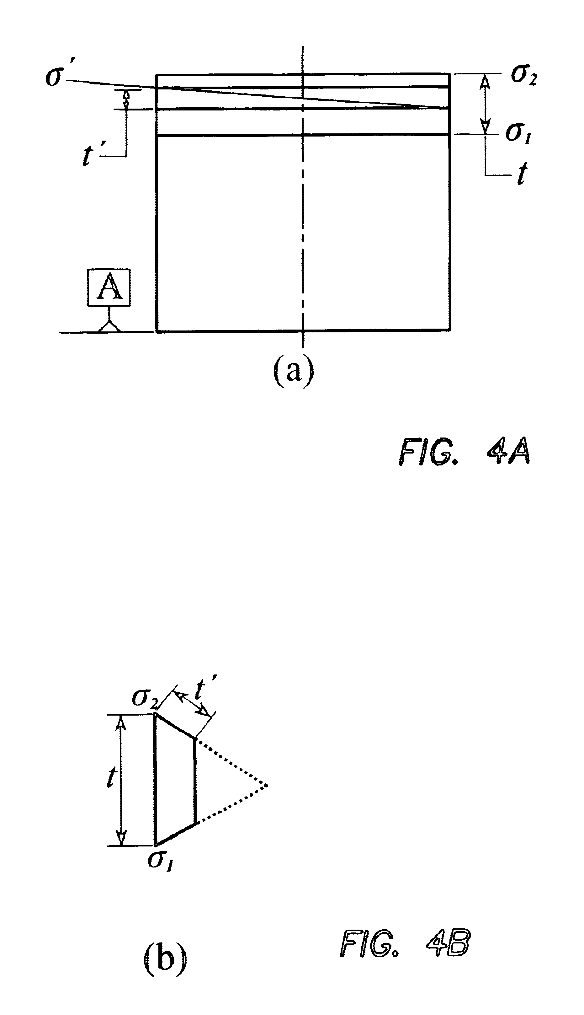
[0073]The invention is a method processing geometric variations which method is rich enough to model all classes of dimensions and tolerances (except free form profile) consistent with tolerance standards and compatible with parametric solid models. A bi-level model is described: one level is for modeling local variations to consider the interaction of all geometric controls (size, form, orientation, position) applied to a feature of interest. The second level is for a global model that inter-relates all control frames on a part or assembly and is needed for software implementation.

[0074]To satisfy conformance to the Y14.5 standard, the model must meet the following criteria:[0075]each tolerance class is represented by regions (zones) whose shape depends on the tolerance type and feature being toleranced and the size depends on the tolerance value, material condition, and Rule # 1;[0076]Rule #1 requires perfect form at maximum material condition (MMC), i.e. form and orientation tole...


PUM


Abstract

The objective of the invention is a bi-level method for modeling geometric tolerances compatible with the ANSI/ASME tolerance standard. At the local level, the model represents each tolerance-zone for a plane or an axis (line) as a tolerance map, and it includes the computational techniques that relate interdependencies between these regions and subregions within them. The model includes formulations for variations in size, form, orientation, position, and runout, and combinations of these, because all of these variations can be modeled using points, lines, and planes. Since variations in simple profiles that are formed from lines and circular arcs also can be described by such combinations, they too are includable in the formulation. The primary method is to overlay the geometry of tolerance-zones onto some traditional modes for representing planes, lines, and points. At the global level, the model inter-relates all frames of reference on a part or an assembly.

Description

RELATED APPLICATIONS[0001]This application is related to U.S. Provisional application Ser. No. 60 / 120,961 filed on Feb. 19, 1999, which is incorporated herein by reference.[0002]Financial assistance for this project was provided by the U.S. Government, National Science Foundation, Grant No. DMI-9821008, and the United States Government may own certain rights to this invention.BACKGROUND OF THE INVENTION[0003]1. Field of the Invention[0004]The invention relates to computer assisted design (CAD) and in particular is a tool for assisting designers in making correct decisions about allocating dimensional and geometric tolerances for proper functioning of precision mechanical parts and assemblies.[0005]2. Description of the Prior Art[0006]Imperfections occur in manufacturing and they must be considered in design so that parts will assemble and function properly. A tolerance specifies the range of imperfections in size and shape that can be permitted for a part to be acceptable when in us...

Claims


Application Information

Patent Timeline
Patent Type & Authority Patents(United States)
IPC IPC(8): G06F17/10G06F17/50
CPCG06F17/50G06F30/00
Inventor DAVIDSON, JOSEPH K.SHAH, JAMI J.MUJEZINOVIE, AMIR
Owner THE ARIZONA BOARD OF REGENTS ON BEHALF OF THE UNIV OF ARIZONA
Why Eureka
Try Eureka