Needle-less injection apparatus and method

a technology of applied in the field of needle-less injection apparatus and method, can solve the problems of more pronounced leakage with each muscle, fluid may continue to leak over several seconds, and the site of injection fluid tends to leak, so as to reduce the amount of tissue, reduce the effect of trauma and reduce the amount of fluid

Inactive Publication Date: 2005-11-15
BOSTON SCI SCIMED INC
View PDF27 Cites 49 Cited by
  • Summary
  • Abstract
  • Description
  • Claims
  • Application Information

AI Technical Summary

Benefits of technology

[0015]By utilizing high pressure needle-less injection, the present invention reduces trauma as compared to needle based systems. In addition, the high pressure needle-less injection system of the present invention reduces fluid leakage from the injection site and distributes injected fluid over a greater volume of tissue.

Problems solved by technology

One limitation to this method of delivering therapeutic agents to the heart is that the injected fluid tends to leak from the site of the injection after the needle is disengaged from the heart.
In fact, fluid may continue to leak over several seconds.
In the case of dynamic organs such as the heart, there may be more pronounced leakage with each muscle contraction.
A second limitation to this method is that the injected fluid remains as a bolus at the injection site and is not distributed over a very wide area.
A third limitation is that needles leave more permanent trauma.
However, it is common for the blood vessels to become occluded (blocked) or stenotic (narrowed).
The torturous path and small diameter of these blood vessels limit access to the stenotic lesions.
The sheer number and small size of these stenotic lesions make techniques such as cardiovascular by-pass surgery, angioplasty, and atherectomy impractical.
A limitation of this procedure is that the therapeutic agent may be quickly carried away by the flow of blood through the heart.
Currently available injection catheters are not particularly suitable for accurately delivering small volumes of therapeutic agents to heart tissue.
This is particularly true for agents carrying genes, proteins, or other angiogenic drugs which may be very expensive, even in small doses.

Method used


Image

  • Needle-less injection apparatus and method
  • Needle-less injection apparatus and method
  • Needle-less injection apparatus and method

Examples


Embodiment Construction

[0024]The following detailed description should be read with reference to the drawings in which similar elements in different drawings are numbered the same. The drawings, which are not necessarily to scale, depict illustrative embodiments and are not intended to limit the scope of the invention.

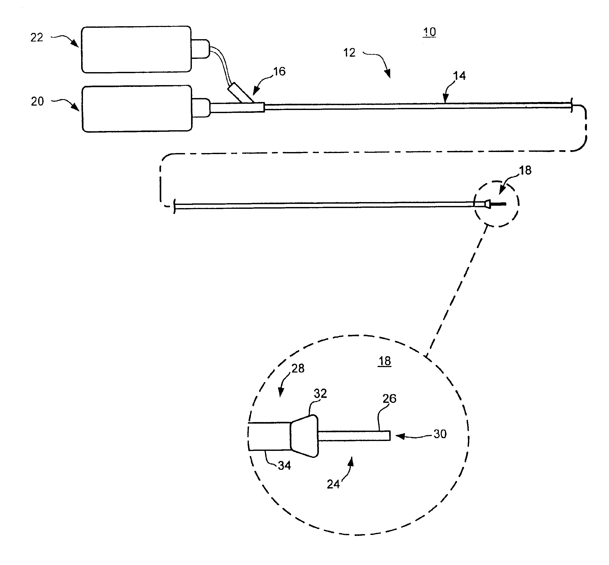
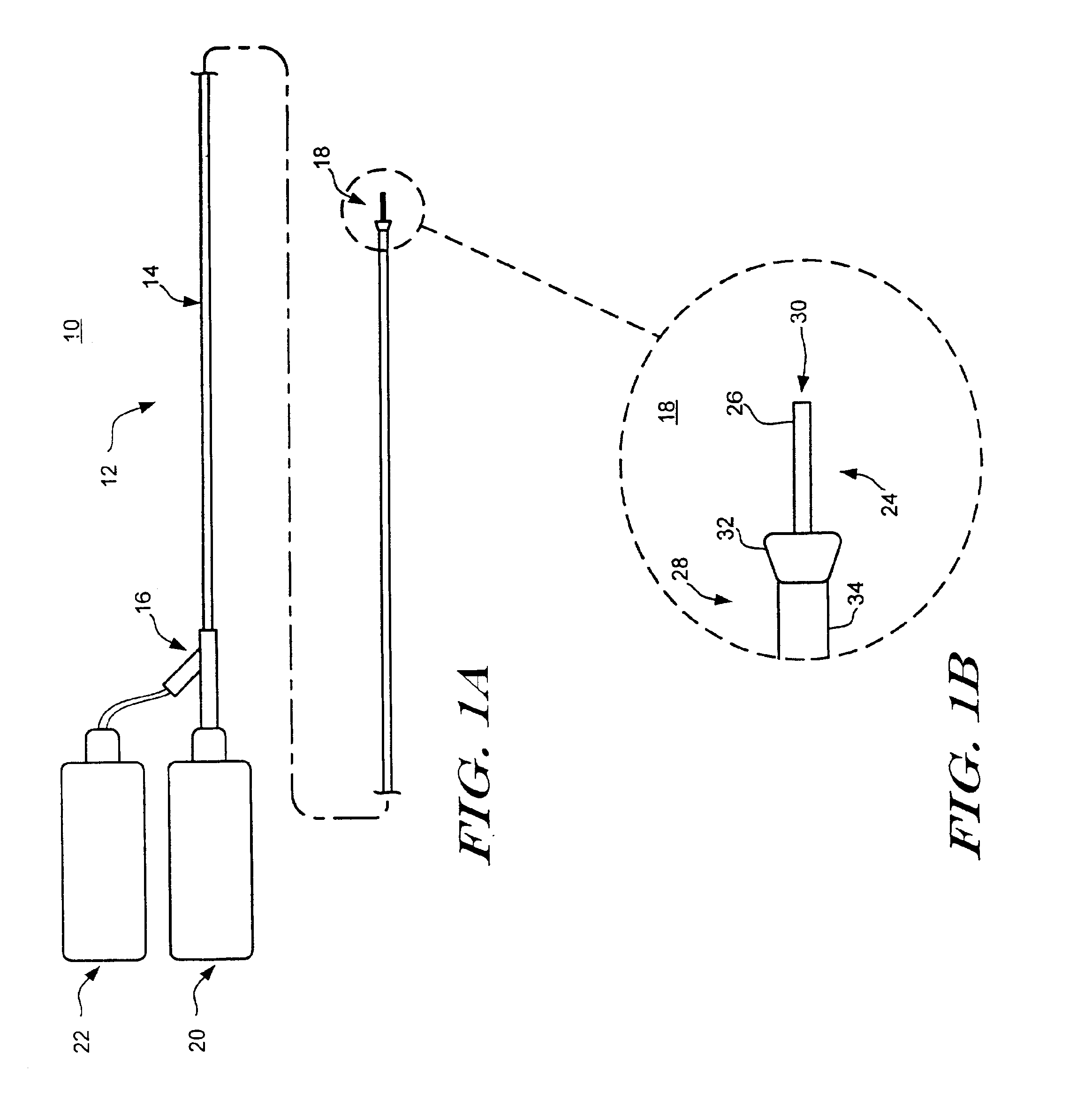
[0025]Refer to FIG. 1A which illustrates a plan view of a catheter system 10 in accordance with an exemplary embodiment of the present invention. Catheter system 10 includes a catheter assembly 12 having an elongate catheter shaft 14. A manifold 16 is connected to the proximal end of the elongate shaft 14. The catheter assembly 12 includes an outer sheath 28 and an inner injection catheter 24, each of which include elongate shafts collectively referred to as elongate shaft 14. The elongate shaft 14 includes a distal portion 18 which is illustrated in greater detail in FIG. 1B.

[0026]The elongate shaft 14 has characteristics (length, profile, flexibility, pushability, trackability, etc.) suita...


PUM


Abstract

A device and method for delivering and injecting fluid into heart tissue utilizing high pressure injection to increase injectate (fluid) retention in the heart tissue. The catheter includes a shaft having an infusion lumen extending therethrough, wherein the proximal end of the shaft connected to a pressurized fluid source capable of generating a transient pressure of more than 1000 psi. The distal end of the shaft includes a nozzle having an injection port in fluid communication with the infusion lumen such that fluid from the pressurized fluid source may be delivered to the heart tissue at a sufficiently high exit velocity to partially penetrate the heart tissue.

Description

RELATED APPLICATIONS[0001]This is a continuation of U.S. patent application Ser. No. 09 / 456,456, filed Dec. 8, 1999, now U.S. Pat. No. 6,344,027. This application is related to patent application Ser. No. 09 / 457,454 filed on Dec. 8, 1999, entitled INJECTION ARRAY APPARATUS AND METHOD, patent application Ser. No. 09 / 457,453 filed on Dec. 8, 1999, entitled LATERAL NEEDLE INJECTION APPARATUS AND) METHOD, and patent application Ser. No. 09 / 457,193 filed on Dec. 8, 1999, entitled LATERAL NEEDLE-LESS INJECTION APPARATUS AND METHOD.FIELD OF THE INVENTION[0002]The present invention generally relates to delivering and injecting fluid into heart tissue. More specifically, the present invention relates to delivering and injecting fluid into heart tissue utilizing needle-less injection.BACKGROUND OF THE INVENTION[0003]Injection catheters may be used to inject therapeutic or diagnostic agents into a variety of organs, such as the heart. In the case of injecting a therapeutic agent into the heart...

Claims


Application Information

Patent Timeline
Patent Type & Authority Patents(United States)
IPC IPC(8): A61B17/22A61M25/00A61M37/00A61B17/00A61M5/30A61M5/32
CPCA61B17/32037A61M25/00A61M25/0068A61M37/00A61B2017/00247A61B2018/00392A61M5/30A61M5/3291A61M2025/0073A61M2025/0081A61M2210/125
Inventor GOLL, J. PAUL
Owner BOSTON SCI SCIMED INC
Why Eureka
Try Eureka