Co-injection apparatus for injection molding

a technology of injection molding and injection molding chamber, which is applied in the field of injection molding apparatus, can solve the problems of non-uniform distribution of materials and structural problems in the end-products

Inactive Publication Date: 2005-12-13
BEMIS MANUFACTURING CO
View PDF34 Cites 25 Cited by
  • Summary
  • Abstract
  • Description
  • Claims
  • Application Information

AI Technical Summary

Benefits of technology

[0006]The invention provides improved co-injection no

Problems solved by technology

But often knit or weld lines (i.e. lines of intersection between materials) develop when using these conventional apparatuses and

Method used


Image

  • Co-injection apparatus for injection molding
  • Co-injection apparatus for injection molding
  • Co-injection apparatus for injection molding

Examples


Embodiment Construction

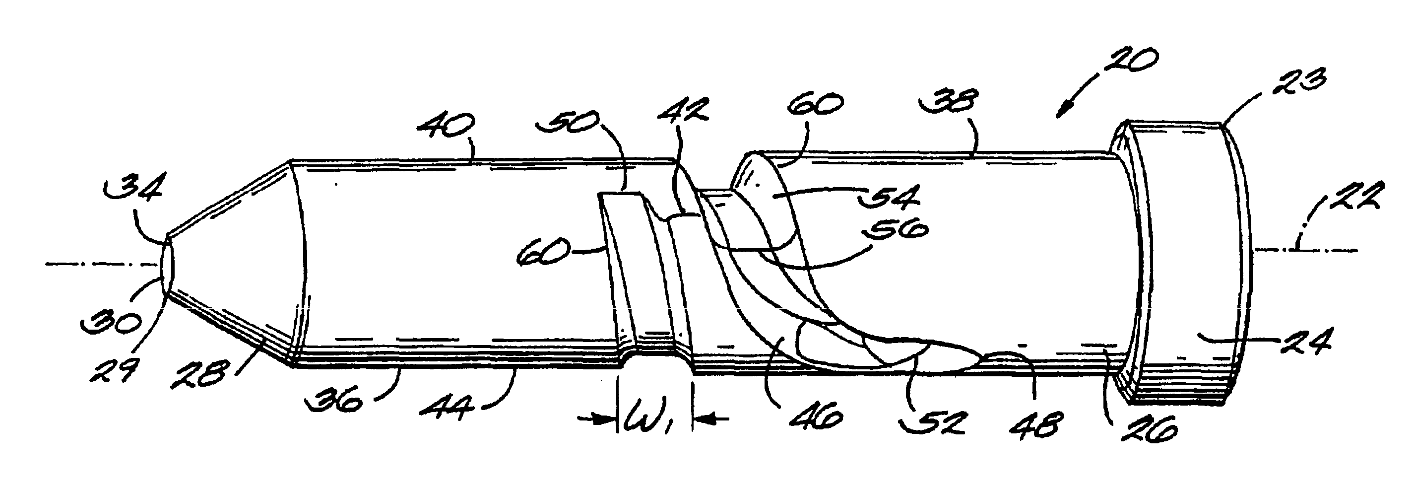
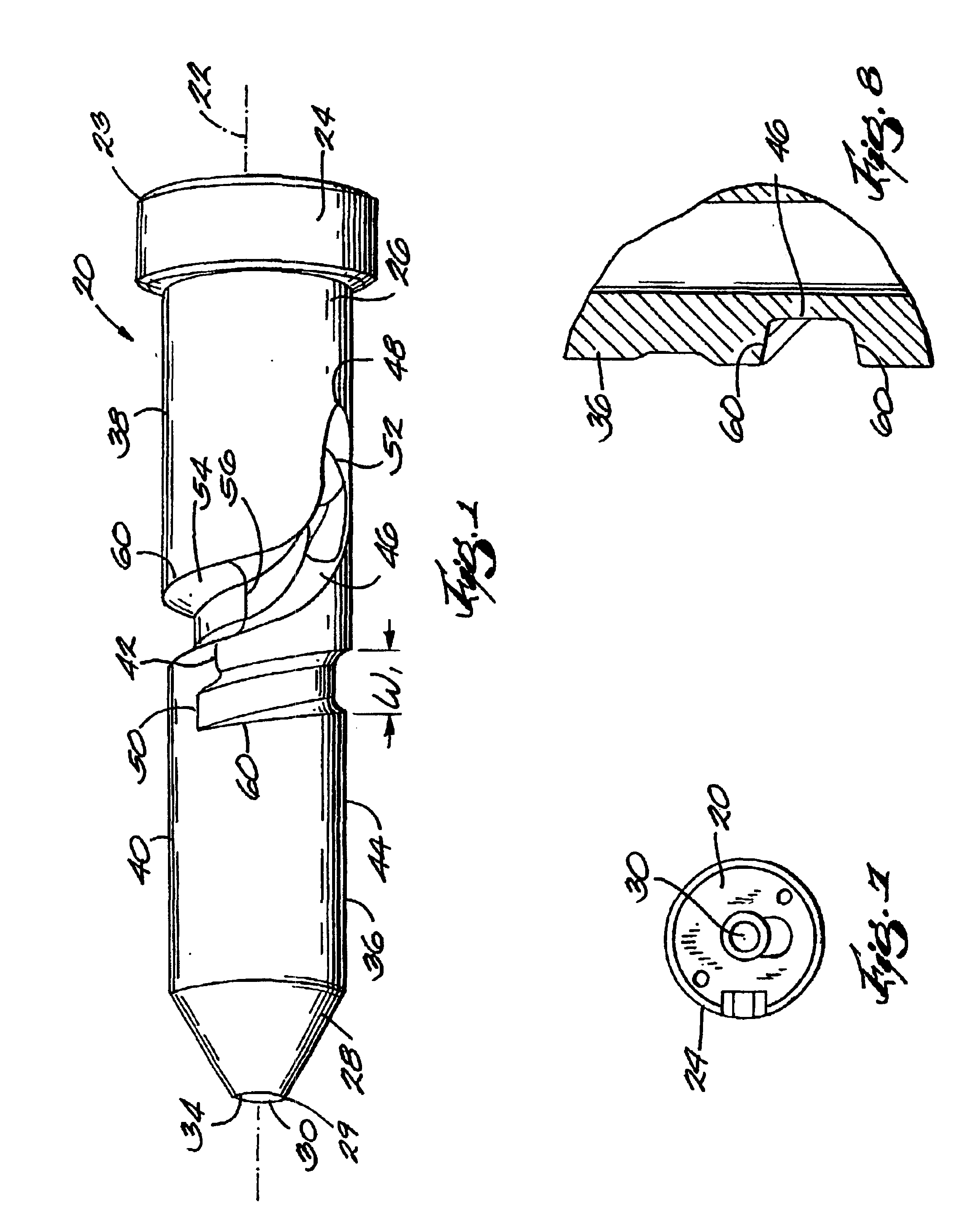
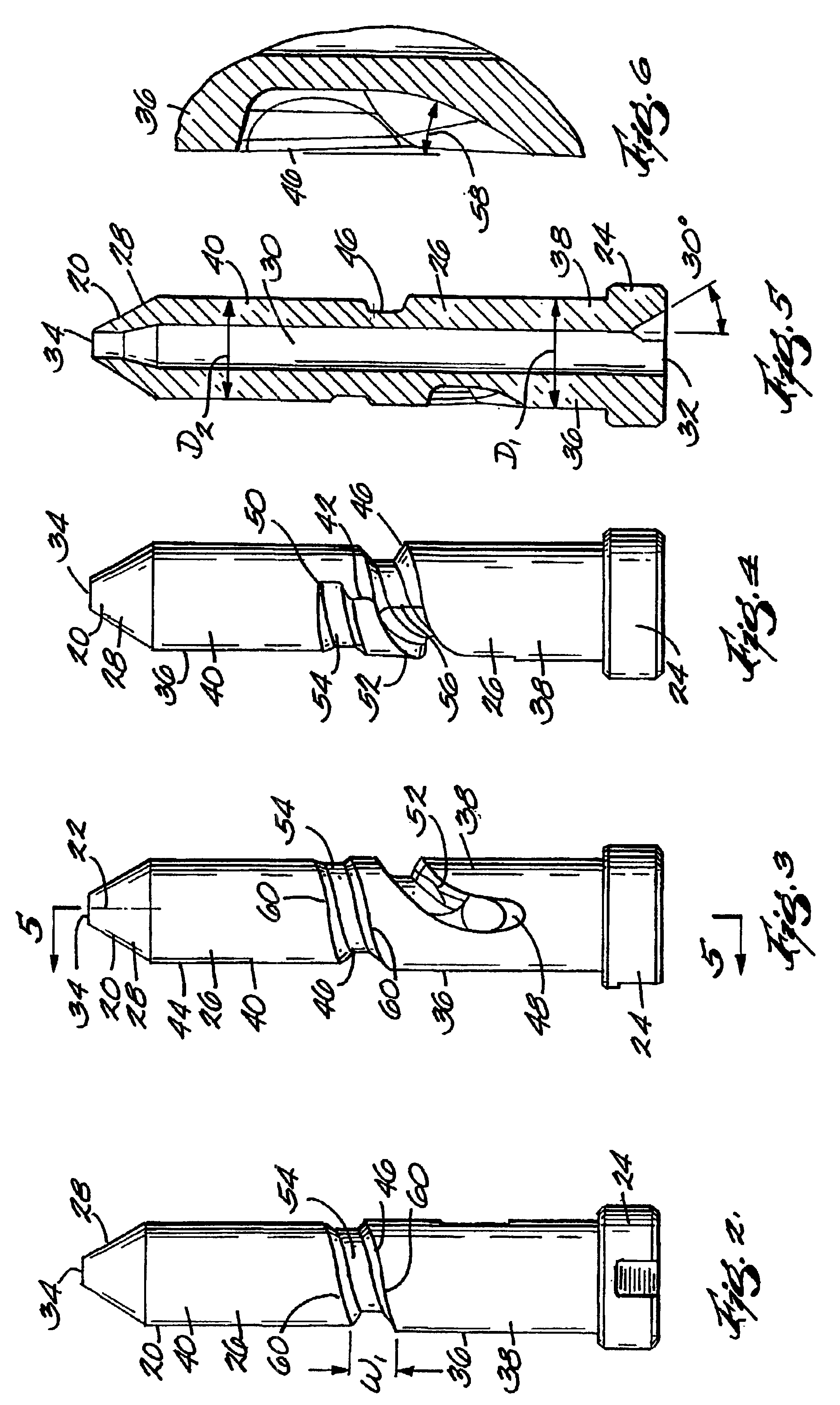
[0021]With reference to FIGS. 1-10, a nozzle pin 20 embodying the invention is shown. The pin 20 is utilized as part of a co-injection apparatus comprising a co-injection manifold, such as the manifold 130 shown and described in U.S. Pat. No. 5,650,178, hereafter referred to as the '178 patent, which issued to Bemis et al. on Jul. 22, 1997, and which is hereby incorporated by reference. The subject matter of the provisional application No. 60 / 186,163 filed Feb. 29, 2000 to which this application claims priority is also incorporated by reference. The apparatus described therein and below is just one example of an apparatus in which the nozzle pin 20 can be used. Use of the nozzle pin is not limited to the apparatus described below. The pin 20 of the present invention is designed to be used in place of the nozzle member 116 of the '178 patent.

[0022]The injection molding apparatus 110 (see FIG. 9) comprises a platen 114. A mold or die 122 is fixed to the platen 114. Any suitable means ...


PUM

PropertyMeasurementUnit
Angleaaaaaaaaaa
Angleaaaaaaaaaa
Flow rateaaaaaaaaaa

Abstract

A co-injection nozzle pin (20) having downstream and upstream ends. The nozzle pin has therein a central bore (30) including an upstream end (32) adapted to communicate with a first material and a downstream end (34) exiting at the downstream end of the pin. The nozzle pin also has an outer surface (36) including a first portion (38) having a diameter D1, a second portion (40) having a diameter D2, wherein D2 is less than D1 and the first portion is rearward of the second portion. The pin further includes a channel (46) spiralling around the outer surface and being adapted to communicate with a second material. The channel (46) includes a first segment (52) defined in the first portion (38) of the outer surface and increasing in depth as it travels in a downstream direction and a second segment (54) defined in the second portion (40) of the outer surface and decreasing in depth as it travels in a downstream direction.

Description

CROSS-REFERENCE TO RELATED APPLICATIONS[0001]This application claims priority under 35 U.S.C. § 119 to provisional patent application No. 60 / 186,163 filed Feb. 29, 2000.FIELD OF THE INVENTION[0002]The invention relates to an injection molding apparatus, and more particularly, to co-injection apparatuses and methods for injecting different materials into a single or multi-cavity mold cavity.BACKGROUND OF THE INVENTION[0003]The invention relates to a nozzle pin used in co-injection apparatuses and methods. A co-injection apparatus injects two different materials, typically an inner-core material and an outer-skin material, into a mold cavity.[0004]A co-injection manifold receives material, usually plastic, from two different injection units and combines the two materials into a single stream that flows into a mold or die. The co-injection manifold, and the co-injection nozzle housed therein, are located between injection units and the single or multi-cavity mold cavity. A typical co-i...

Claims


Application Information

Patent Timeline
IPC IPC(8): B29C45/16
CPCB29C45/1603B29C2045/308
Inventor BEMIS, PETER F.KOLSTE, STEVEN J.CYKANA, DANIELFIACCHINO, STEPHEN R.O'GRADY, MICHAEL P.
Owner BEMIS MANUFACTURING CO
Why Eureka
Try Eureka