Method for fine bore orifice spray coating of medical devices and pre-filming atomization

a technology of fine bore orifice and spray coating, applied in the direction of packaging goods, pharmaceutical containers, foodstuffs, etc., can solve the problems of vibration affecting the stability of the spray nozzle used in both spraying and electrostatic spray coating, indiscriminate and/or difficult control of the conventional coating process, etc., to achieve stability and reduce coating variability, the effect of reducing vibration

Active Publication Date: 2005-12-27
BOSTON SCI SCIMED INC
View PDF6 Cites 12 Cited by
  • Summary
  • Abstract
  • Description
  • Claims
  • Application Information

AI Technical Summary

Benefits of technology

[0014]In certain embodiments of the invention, a method is provided for applying a coating material with a spray coating fluid delivery apparatus having a constricting outlet nozzle orifice with a fine bore diameter. This fine bore nozzle orifice increases back pressure of the coating material within the spray apparatus and chokes the coating material supply line, thereby dampening the vibration of the apparatus, resulting in a more stable spray plume of coating, a smaller spray droplet size for enhanced atomization, and a more uniform coating application.
[0015]In another embodiment of the present invention, a method for stabilizing a spray plume of a spray apparatus is provided in which the coating material flows from a fine bore nozzle orifice onto an adjacent surface thereby creating a thin film layer of coating material at an angle to the directional flow of the atomizing fluid. Edge portions of the thin film are then entrained within the high velocity atomizing fluid as the atomizing fluid flows by the edge of the flat surface. This pre-filming step permits a more stable plume having a finer spray droplet with less size variance.
[0016]In another embodiment of the present invention, a method for atomizing a coating material into fine spray droplets is provided that includes a pre-filming step in which a film layer of coating material is thinly spread upon a surface. A portion of that film layer is then entrained within the high velocity atomizing fluid to improve atomization.
[0018]The present invention provides a method and apparatus to provide one or more benefits such as to damp out vibration, stabilize the spray plume, reduce coating variability, and / or reduce coating material spray droplet size, leading to improved coating material transfer and uniformity in a more cost-efficient manner.

Problems solved by technology

These conventional coating processes are often, however, indiscriminate and / or difficult to control.
For example, dipping can result in non-uniform application of the coating to the device because gravity and longer exposure time may cause more coating to be applied at one end or region of the device, thus the coating may be thicker at one end.
With respect to conventional spray coating and electrostatic spray deposition, empirical experience has shown that the spray plume stability of a spray nozzle used in both spraying and electrostatic spray coating is affected by vibration.
Instability in the spray plume caused by vibration can cause variability in coating thickness and weight and reduce manufacturing reproducibility.
Additionally, the venturi effect of the atomizing fluid may pull more coating fluid from the spray nozzle, which further limits controllability over the spray plume.
In addition, conventional spray nozzles typically provide a wide range of spray droplet sizes, which increases coating variance.
Further, conventional spray nozzles typically have a dome-shaped nozzle geometry which limits controllability of spray droplet size as the coating material is pulled directly from the orifice due to the venturi effect of the atomizing fluid.
Such variability could be detrimental to obtaining consistent coating distribution and thickness on the target, making it difficult to predict the dosage of therapeutic that will be delivered when the medical device or stent is implanted.

Method used


Image

  • Method for fine bore orifice spray coating of medical devices and pre-filming atomization
  • Method for fine bore orifice spray coating of medical devices and pre-filming atomization
  • Method for fine bore orifice spray coating of medical devices and pre-filming atomization

Examples


Embodiment Construction

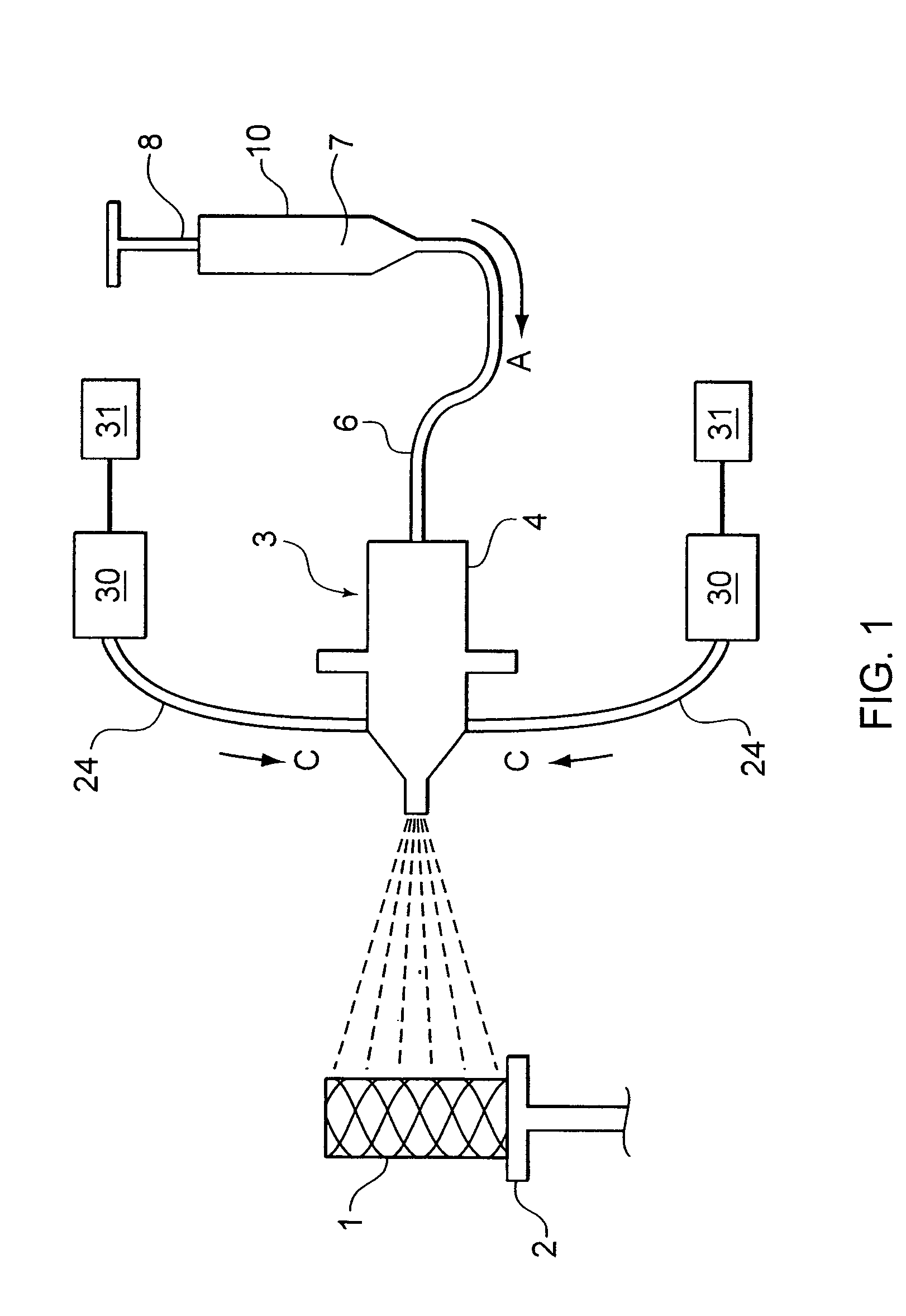
[0024]A first embodiment of the present invention is illustrated in FIG. 1. In this embodiment, a target 1 to be coated with a coating fluid is held by target holder 2. Target 1 in this instance is a stent that is to be coated with a therapeutic material. Stent holder 2 may hold stent 1 by any number of means, such as by the stent holders described in U.S. patent application Ser. No. 10 / 198,094, which shares a common assignee to the pending application at bar, and the disclosure of which is hereby expressly incorporated by reference herein.

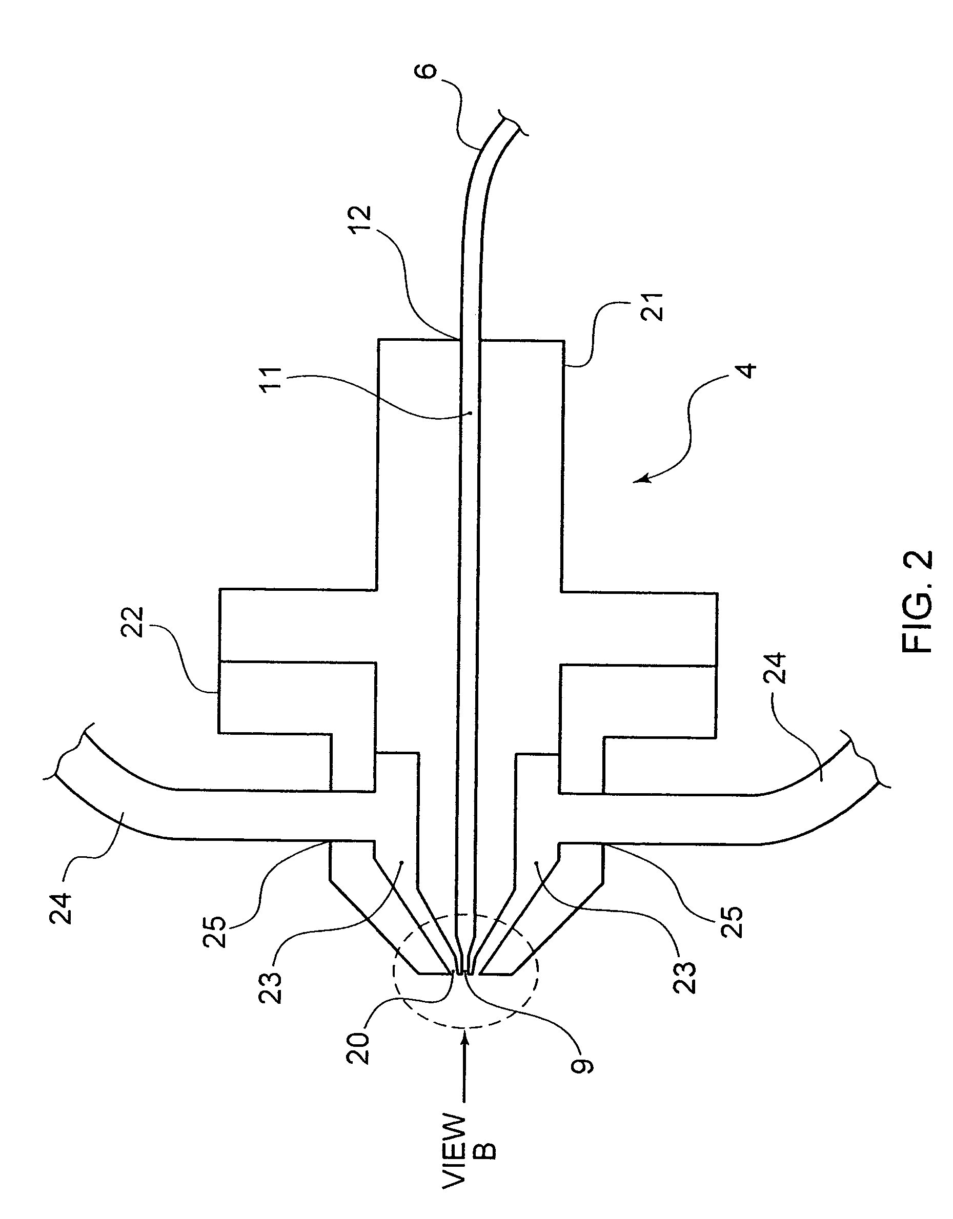
[0025]Proximate to stent 1 and holder 2 is a spray coating fluid delivery device 3, schematically illustrated in FIG. 1. Spray delivery device 3 includes a nozzle body 4, coating fluid reservoir 7, a coating fluid supply line 6 in fluid communication with a coating fluid reservoir 7 and nozzle body 4, atomizing fluid reservoir 30, and an atomizing fluid supply line 24 in fluid communication with atomizing fluid reservoir 30 and nozzle body 4. The ...


PUM


Abstract

A method for spray deposition of small targets, such as medical devices like stents. The method includes the steps of positioning a spray nozzle body, which has a fine bore diameter to pressurize the coating material within the nozzle body, near a medical device, and dampening vibration of the nozzle body during operation by maintaining a steady back pressure in the coating material line sufficient to eliminate or minimize vibration modes from external and internal sources; and stabilizing the spray coating plume. In another embodiment, a coating method is disclosed in which a finer atomized spray droplet size is achieved by pre-filming the coating material onto a flat face before entraining the coating material within the atomizing fluid, which improves manufacturing repeatability, reduces coating variances, and increases therapeutic dosage predictability. In certain embodiments of the invention, the coating materials include therapeutic agents and biologically active materials.

Description

FIELD OF THE INVENTION[0001]The field of the present invention involves the application of coatings to target devices, such as medical devices. More specifically, the present invention is directed to the field of spray coating a fluid, such as a therapeutic or protective coating fluid, onto a target device.BACKGROUND[0002]The positioning and deployment of medical devices within a patient is a common, often-repeated procedure of contemporary medicine. Such medical devices or implants are used for innumerable medical purposes, including the reinforcement of recently re-enlarged lumens, or the replacement of ruptured vessels.[0003]Coatings are often applied to the surfaces of these medical devices to increase their effectiveness. These coatings may provide a number of benefits including reducing the trauma suffered during the insertion procedure, facilitating the acceptance of the medical device into the target site, and improving the post-procedure effectiveness of the device.[0004]Co...

Claims


Application Information

Patent Timeline
Patent Type & Authority Patents(United States)
IPC IPC(8): B05B7/06
CPCB05B7/066
Inventor O'CONNOR, TIMSOBRINO, GABRIEL
Owner BOSTON SCI SCIMED INC
Why Eureka
Try Eureka