Method and system of remote diagnostic, control and information collection using a dynamic linked library of multiple formats and multiple protocols with restriction on protocol
What is AI technical title?
AI technical title is built by PatSnap AI team. It summarizes the technical point description of the patent document.
a dynamic linking and information collection technology, applied in the field of methods and systems of remote diagnostics, control and information collection, can solve problems such as warning conditions and error conditions
Inactive Publication Date: 2006-01-17
RICOH KK
View PDF27 Cites 64 Cited by
Summary
Abstract
Description
Claims
Application Information
AI Technical Summary
This helps you quickly interpret patents by identifying the three key elements:
Problems solved by technology
Method used
Benefits of technology
Benefits of technology
[0012]One object of the present invention is to provide a novel and effective system for monitoring events of a target application of an application unit.
[0014]A further object of the present invention is to provide a system for communicating data obtained by monitoring events of a target application of an application unit to a remote party allowing various data formats and communication protocols to facilitate the communication system configuration and received data analysis.
[0015]A further object of the present invention is to provide a system for communicating data obtained by monitoring events of a target application of an application unit to a remote party allowing various data formats that ease the analyses of received data at the receiving side.
[0016]A further object of the present invention is to efficiently communicate the monitored event information to a transmission unit.
[0017]A further object of the present invention is to efficiently verify the combination of the two parameters specifying the format and protocol and to meet the restriction requirement on the second parameter.
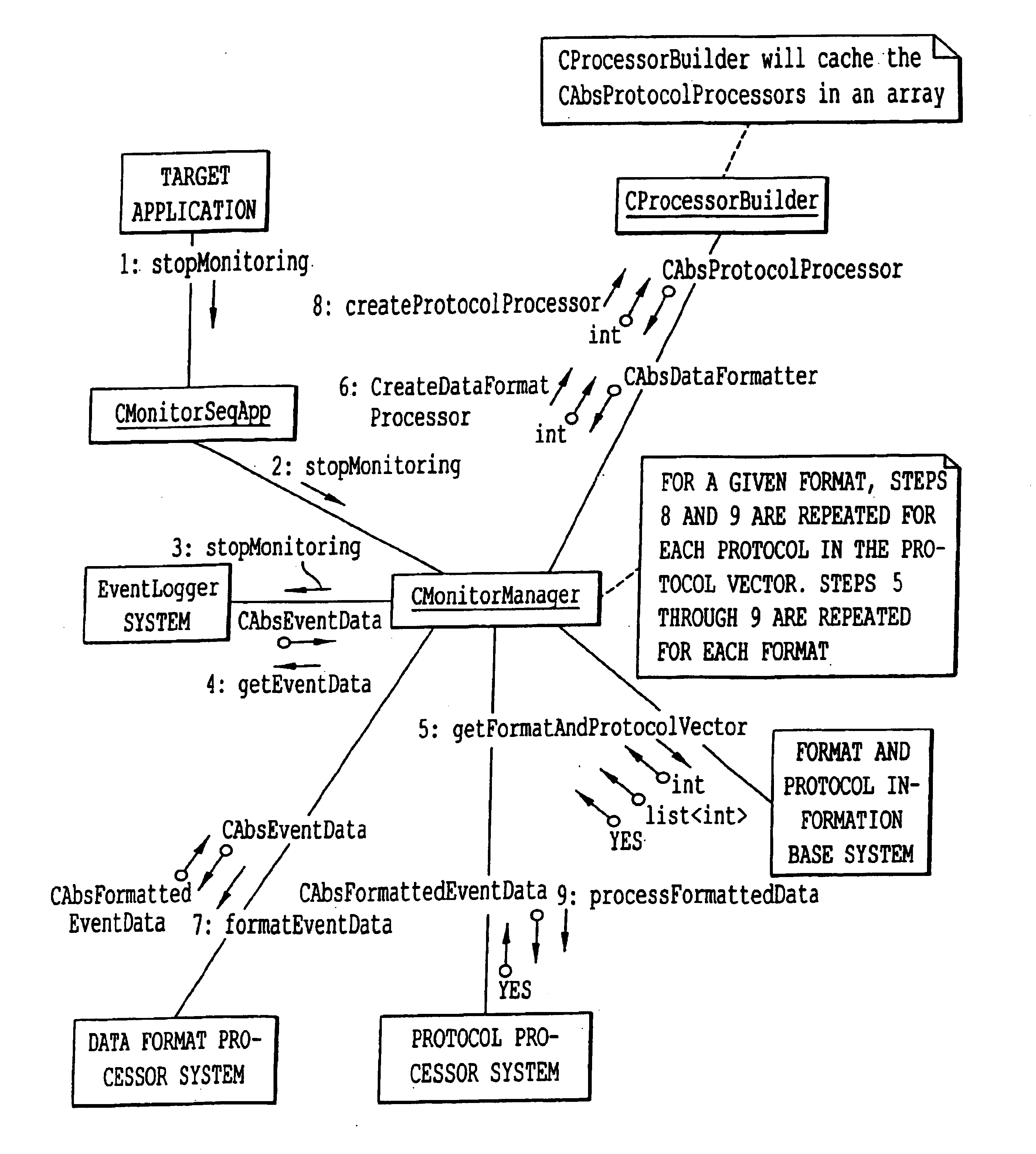
[0018]The present invention achieves these and other objects by monitoring the events of a target application of an application unit. Monitoring examples include (1) monitoring a software program being executed on a computer or workstation under control of a user, (2) monitoring usage of a control panel of an image forming apparatus (e.g., a copyingmachine, printer, facsimile, or scanner), an appliance (e.g., a microwave oven, VCR, digital camera, cellular phone, or palm top computer), (3) monitoring any internal state changes such as error conditions and warning conditions within appliances, devices and any systems and sending the results when requested or when events occur or when preset time interval occurs, (4) externally monitoring states of appliances, devices or system by polling at regular interval, and (5) generally monitoring any other device or service. The data obtained by monitoring events of a target application of an application unit, appliance, or device can, as a further feature in the present invention, be collected, logged and communicated to a desired location by a store-and-forward protocol (e.g., Internet e-mail) or a “direct” connection protocol in which a socket connection is made to an ultimate destination machine (e.g., using FTP or HTTP). The use of store-and-forward communication reduces the costs associated with communicating such data. The data can be communicated to the desired location at several instances. Such instances include each time a user exits a target application, or after a predetermined number of times that a user has utilized and exited the target application of the application unit. If the configuration allows and if necessary, the direct connection between the monitored application and the monitoring system can be established in addition to the store-and-forward communication.
Problems solved by technology
Some events may be caused by abnormal conditions such as paper jam in the copiers.
Some error conditions and warning conditions may be caused by errors in the software installed in the target appliances and devices.
Method used
Image
Click on the blue label to locate the original text in one second.
Reading with bidirectional positioning of images and text.
Examples
Embodiment Construction
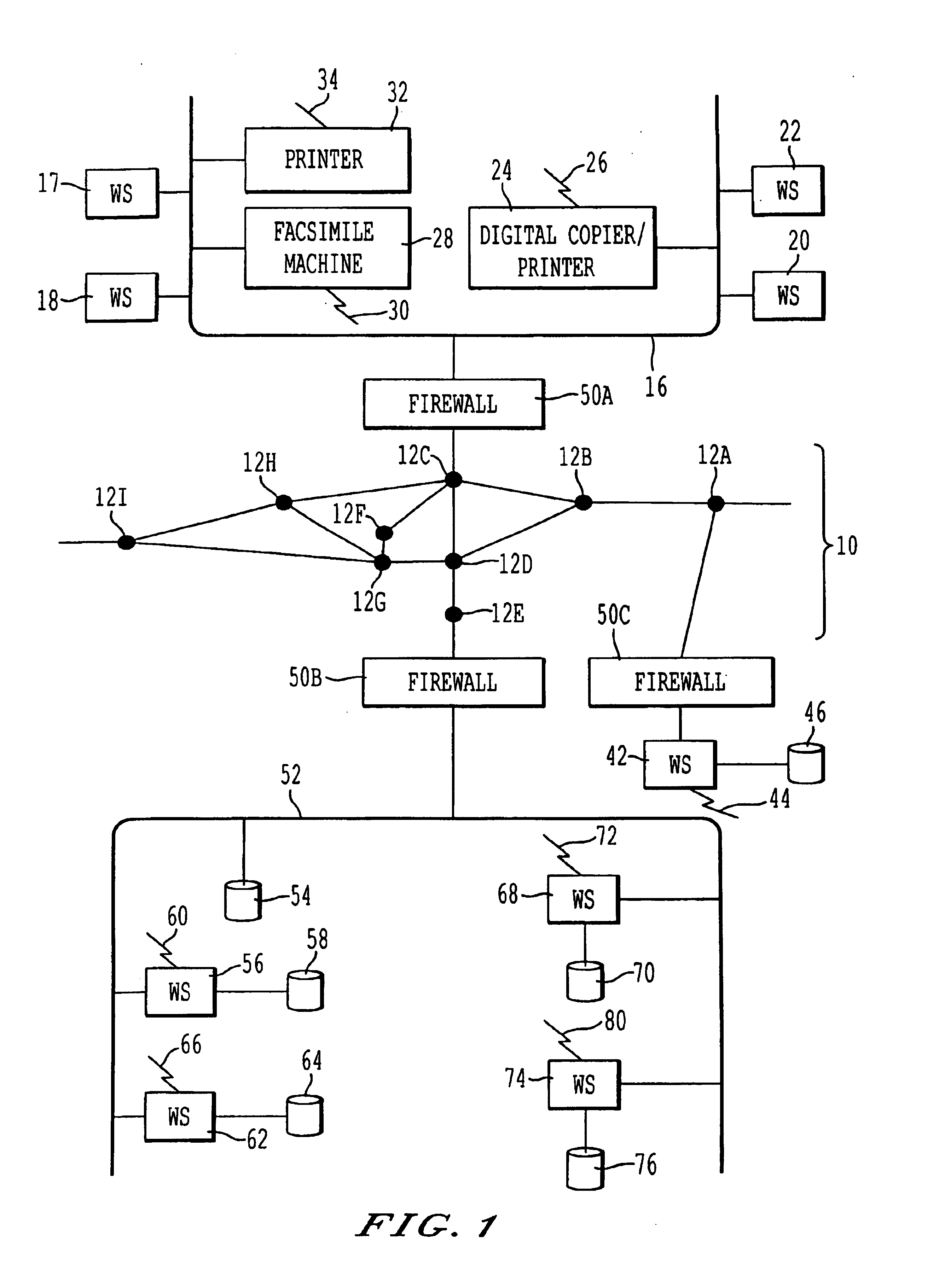
[0050]Referring now to the drawings, wherein like reference numerals designate identical or corresponding parts throughout the several views, FIG. 1 illustrates (1) various machines and (2) computers for monitoring, diagnosing and controlling the operation of the machines. In FIG. 1, there is a first network 16, such as a Local Area Network (LAN) connected to computer workstations 17, 18, 20 and 22. The workstations can be any type of computers including IBM Personal Computer compatible devices, Unix-based computers, or Apple Macintoshes. Also connected to the network 16 are (1) a digital image forming apparatus 24, (2) a facsimilemachine 28, and (3) a printer 32. As would be appreciated by one of ordinary skill in the art, two or more of the components of the digital image forming apparatus 24.and the facsimile machine 28 can be combined into a unified “image forming apparatus.” The devices 24, 28 and 32 and the workstations 17, 18, 20 and 22 are referred to as machines or monitor...
PUM
Abstract
A method, system and computer program product for (1) collecting information from a remote application unit and / or (2) diagnosing or controlling the remote application unit. By utilizing a shareable computer code device (e.g., a dynamic linked library), a new application can utilize tested, proven code without having to reproduce existing functionality. Moreover, by supporting multiple data formats and / or multiple communication protocols, a computer code device increases the likelihood that a supported format and / or protocol will be either receivable or understandable by a receiver.
Description
CROSS-REFERENCE TO RELATED APPLICATIONS[0001]The present application is related to the following U.S. applications and patents: application Ser. No. 09 / 440,692 of 1999 Nov. 16; application Ser. No. 09 / 440,647 of 1999 Nov. 16, now U.S. Pat. No. 6,662,225; application Ser. No. 09 / 440,646 of 1999 Nov. 16; application Ser. No. 09 / 440,693 of 1999 Nov. 16; application Ser. No. 09 / 440,645 of 1999 Nov. 16; application Ser. No. 09 / 408,443 of 1999 Sept. 29, now U.S. Pat. No. 6,631,247; application Ser. No. 09 / 407,769 of 1999 Sept. 29, now U.S. Pat. No. 6,581,092; application Ser. No. 09 / 393,677 of 1999 Sep. 10; application Ser. No. 09 / 311,148 of 1999 May 13; application Ser. No. 09 / 192,583 of 1998 Nov. 17; application Ser. No. 09 / 190,460 of 1998 Nov. 13, now U.S. Pat. No. 6,208,956; application Ser. No. 08 / 883,492 of 1997 Jun. 26; application Ser. No. 09 / 108,705 of 1998 Jul. 1; application Ser. No. 09 / 107,989 of 1998 Jul. 1, now U.S. Pat. No. 6,801,331; application Ser. No. 08 / 997,482 of 1997...
Claims
Application Information
Patent Timeline
Application Date:The date an application was filed.
Publication Date:The date a patent or application was officially published.
First Publication Date:The earliest publication date of a patent with the same application number.
Issue Date:Publication date of the patent grant document.
PCT Entry Date:The Entry date of PCT National Phase.
Estimated Expiry Date:The statutory expiry date of a patent right according to the Patent Law, and it is the longest term of protection that the patent right can achieve without the termination of the patent right due to other reasons(Term extension factor has been taken into account ).
Invalid Date:Actual expiry date is based on effective date or publication date of legal transaction data of invalid patent.

