Illumination system

a technology of illumination system and illumination device, which is applied in the direction of identification means, lighting applications, instruments, etc., can solve the problems of not describing the illumination system that provides efficient and highly recognizable devices for producing light, and achieves low manufacturing cost, easy and efficient manufacturing and marketing, and durable and reliable construction

Inactive Publication Date: 2006-01-31
TWR LIGHTING
View PDF14 Cites 88 Cited by
  • Summary
  • Abstract
  • Description
  • Claims
  • Application Information

AI Technical Summary

Benefits of technology

[0022]It is therefore an object of the present invention to provide a new and improved illumination system which has all of the advantages of the prior art illumination systems of known designs and configurations and none of the disadvantages.
[0023]It is another object of the present invention to provide a new and improved illumination system which may be easily and efficiently manufactured and marketed.
[0024]It is further object of the present invention to provide a new and improved illumination system which is of durable and reliable constructions.
[0025]An even further object of the present invention is to provide a new and improved illumination system which is susceptible of a low cost of manufacture with regard to both materials and labor, and which accordingly is then susceptible of low prices of sale to the consuming public, thereby making such illumination system economically available.
[0026]Even still another object of the present invention is to provide an illumination system for providing efficient and highly recognizable devices for producing light.

Problems solved by technology

While the prior art devices fulfill their respective, particular objectives and requirements, they do not describe illumination system that provides efficient and highly recognizable devices for producing light.

Method used


Image

  • Illumination system
  • Illumination system
  • Illumination system

Examples


Embodiment Construction

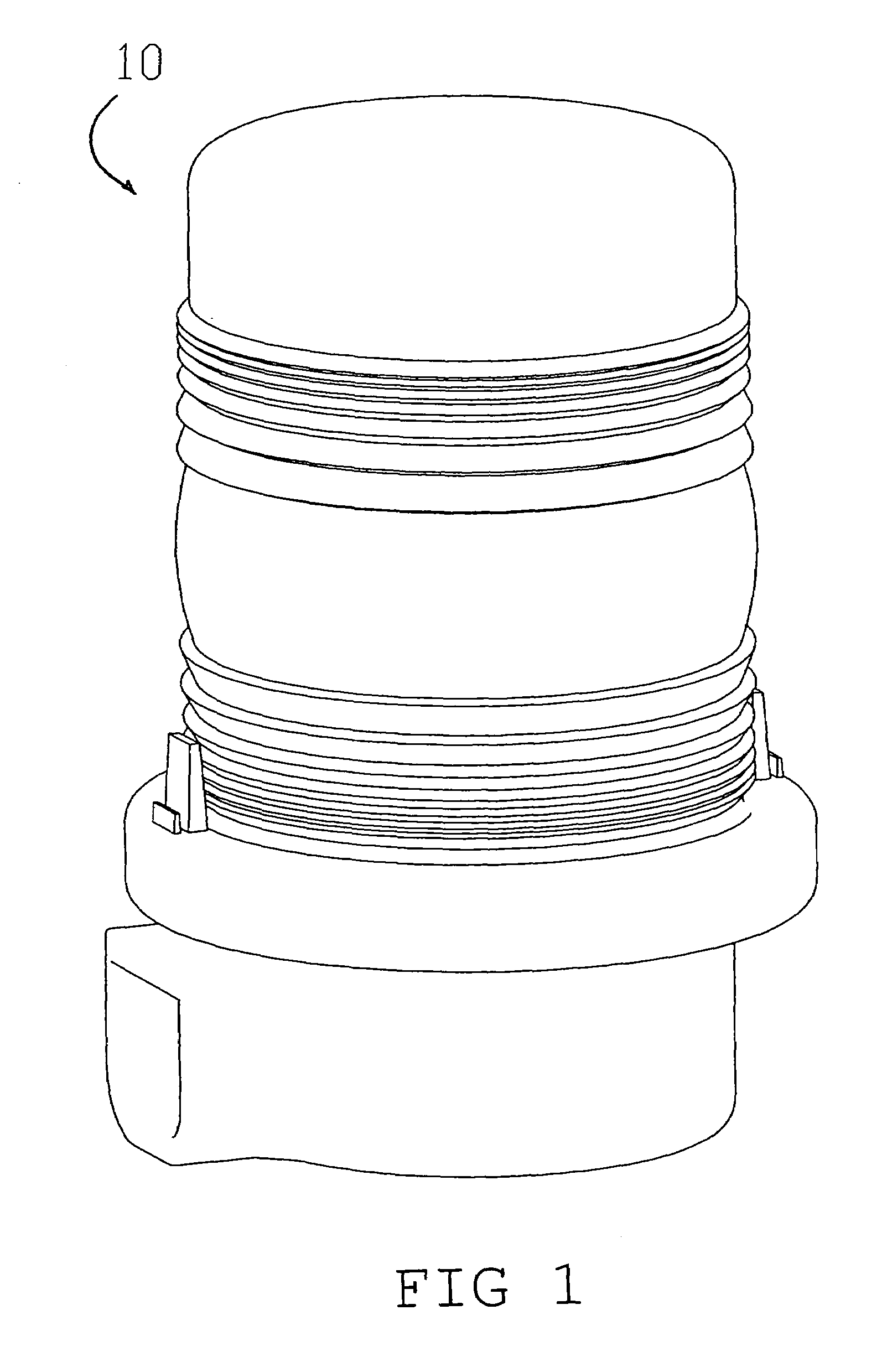
[0039]With reference now to the drawings, and in particular to FIG. 1 thereof, the preferred embodiment of the new and improved illumination system embodying the principles and concepts of the present invention and generally designated by the reference numeral 10 will be described.

[0040]The present invention, the illumination system 10 is comprised of a plurality of components. Such components in their broadest context include a circular mounting plate, a plurality of thermally conductive circuit boards, a plurality of light emitting diodes, an optical lens formed and a lamp base. Such components are individually configured and correlated with respect to each other so as to attain the desired objective.

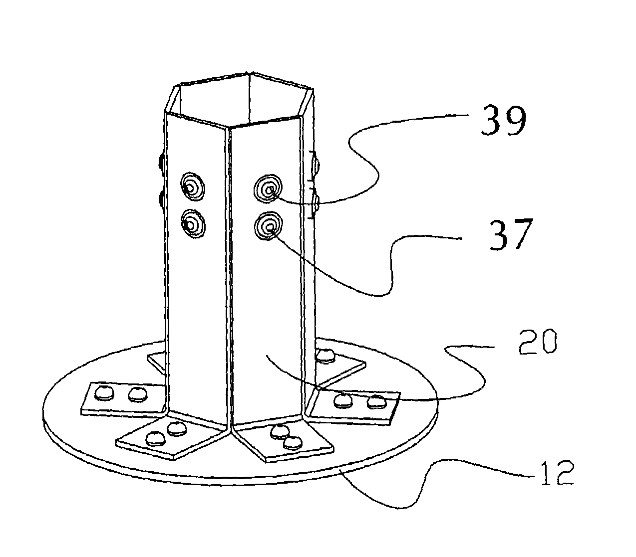
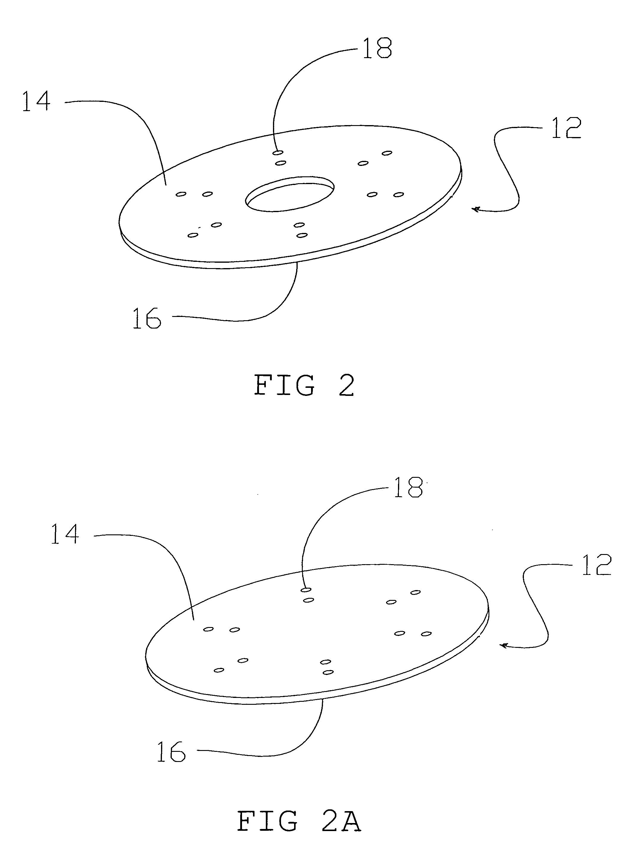
[0041]The present invention essentially comprises a thin circular plate 12 comprised of thermally conductive material. The circular plate has an upper surface 14 and a lower surface 16 with a plurality of radially paired apertures 18 extending there through and located equally spaced ...


PUM


Abstract

An illumination system has a mounting plate, a plurality of thermally conductive circuit boards in thermal contact with the mounting plate, a plurality of light emitting diodes electrically and thermally communicating with the circuit board strips, an optical lens formed as a translucent dome covering the circuit boards and light emitting diodes, and a lamp base operatively coupled to the mounting plate and circuit boards. The light emitting diodes receive power from an external electrical source entering the system through the base and the circuit boards.

Description

BACKGROUND OF THE INVENTION[0001]1. Field of the Invention[0002]The present invention relates to an illumination system and more particularly pertains to providing efficient and highly recognizable devices for producing light.[0003]2. Description of the Prior Art[0004]The use of illumination systems of known designs and configurations is known in the prior art. More specifically, illumination systems of known designs and configurations previously devised and utilized for the purpose of providing recognizable devices for producing light are known to consist basically of familiar, expected, and obvious structural configurations, notwithstanding the myriad of designs encompassed by the crowded prior art which has been developed for the fulfillment of countless objectives and requirements.[0005]By way of example, U.S. Pat. No. 6,425,678 issued Jul. 30, 2002 to Verdes.[0006]While the prior art devices fulfill their respective, particular objectives and requirements, they do not describe ...

Claims


Application Information

Patent Timeline
Patent Type & Authority Patents(United States)
IPC IPC(8): B60Q1/06F21V29/00
CPCB60Q1/2611F21V29/004F21V29/2212F21V29/85F21V29/74F21V19/001F21Y2101/02F21Y2111/005F21W2111/06F21Y2115/10F21Y2107/30F21V29/767F21V19/0035
Inventor PETRICK, JOHN T.
Owner TWR LIGHTING
Why Eureka
Try Eureka