Magnetic recording and reproducing device

a recording and reproducing device technology, applied in the field of magnetic recording and reproducing devices, can solve the problems of unbalanced outputs of two magnetic heads, undesirable generation of head pick-up signals on adjacent tracks upon reproducing data, and large loss of transfer, so as to achieve the margin of an rf output, the effect of less electromagnetic conversion between channels and improved recording density

Inactive Publication Date: 2006-03-07
SONY CORP
View PDF9 Cites 3 Cited by
  • Summary
  • Abstract
  • Description
  • Claims
  • Application Information

AI Technical Summary

Benefits of technology

[0014]The present invention is proposed by taking the above-described problems into consideration and it is an object of the present invention to reduce an output difference between two magnetic heads while the loss of electromagnetic conversion is reduced in a magnetic recording and reproducing device in which a evaporated tape is used, an azimuth recording is carried out, a track pitch is not larger than 5 μm and the shortest recording wavelength is not larger than 0.3 μm.
[0018]Accordingly, in the helical scanning drive type magnetic recording and reproducing device using the obliquely evaporated tape, while the loss of electromagnetic conversion between channels is reduced, the balance of outputs between a first channel and a second channel can be obtained. Thus, a recording density is more improved and the margin of an RF output can be obtained.

Problems solved by technology

However, a cross-talk that the head picks up a signal on the adjacent track upon reproducing data is undesirably generated.
An azimuth is set so that a great transfer loss is undesirably generated in an electromagnetic conversion in one magnetic head.
Accordingly, for instance, as shown in FIG. 4, RF outputs of the two magnetic heads are unbalanced.
Thus, the efficiency of the RF output is not good as the magnetic recording and reproducing system.
A magnetic recording and reproducing system which has been usually used has not good efficiency under its recording density, but meets only the improvement of the performance of a media head.
Therefore, there is a large level difference between the RF outputs of the 1ch head and the 2ch head, which has a great unbalance.

Method used


Image

  • Magnetic recording and reproducing device
  • Magnetic recording and reproducing device
  • Magnetic recording and reproducing device

Examples


Embodiment Construction

[0023]Now, an embodiment of the present invention will be described below in detail by referring to the drawings. It is to be understood that the present invention is not limited to the embodiment. A magnetic recording and reproducing device according to this embodiment is applied to a magnetic recording and reproducing device comprising a thin film type head for any of recording and reproducing heads forming a first magnetic head and a second magnetic head and an obliquely evaporated magnetic tape on which an azimuth recording is carried out with a track pitch of not larger than 5 μm and the shortest recording wavelength of not larger than 0.3 μm.

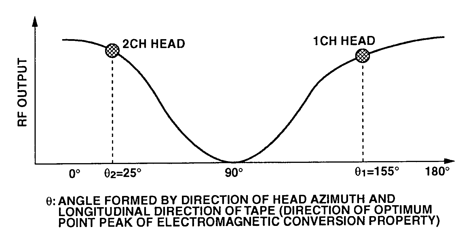
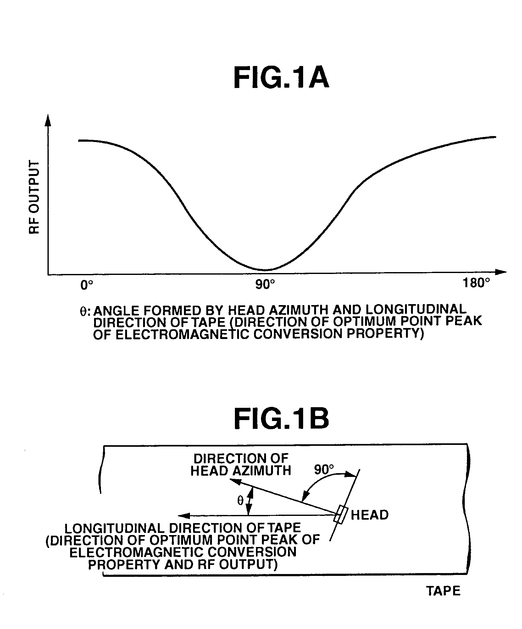
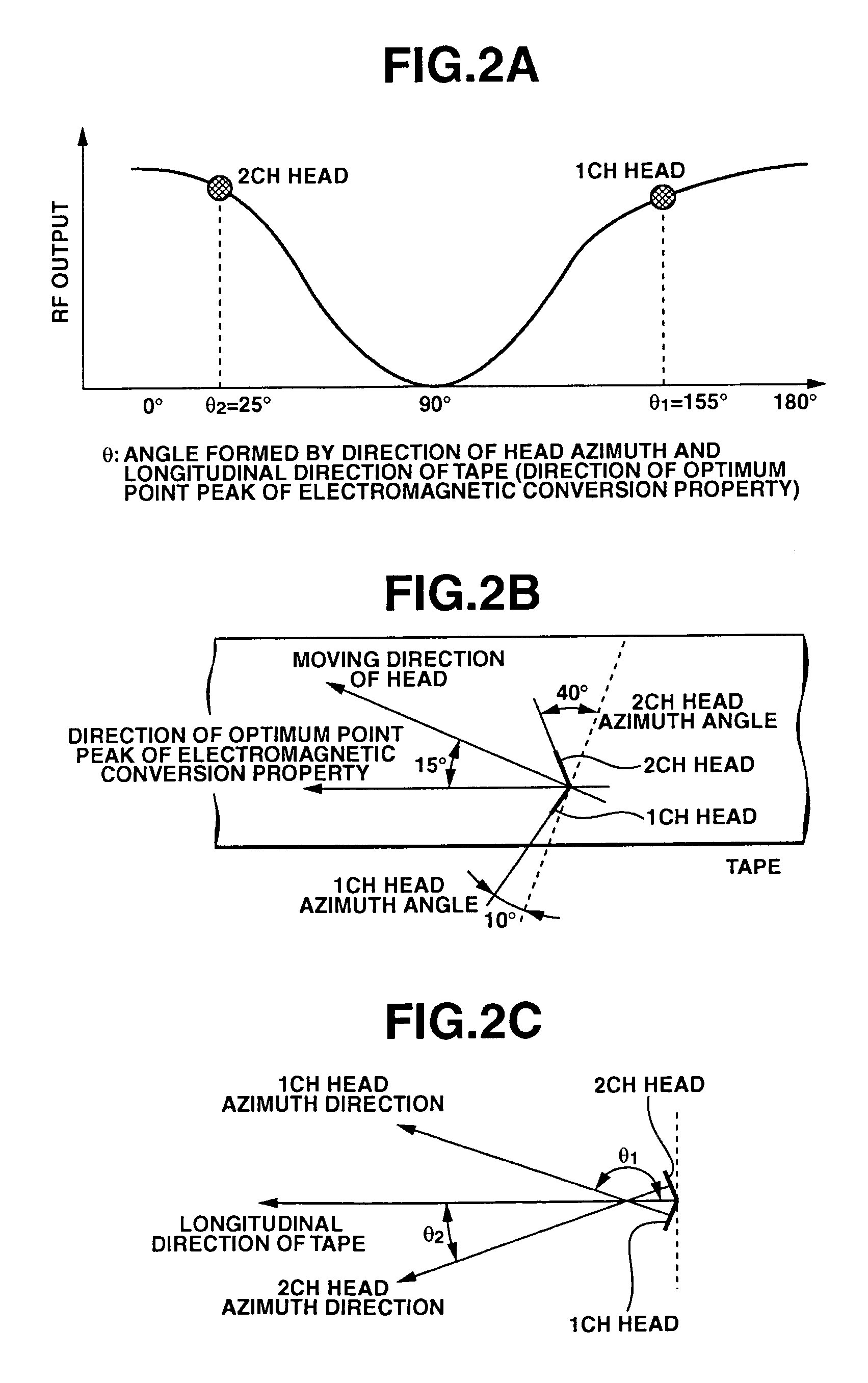
[0024]The obliquely evaporated magnetic tape is most suitable for improving a high recording density. However, as shown in FIG. 1, there is an optimum point peak of an electromagnetic conversion property in the longitudinal direction of the tape. Further, a direction of a head azimuth and an RF output satisfy a relation expressed by RF out...


PUM

PropertyMeasurementUnit
angleaaaaaaaaaa
angleaaaaaaaaaa
azimuth anglesaaaaaaaaaa

Abstract

In a magnetic recording and reproducing device having a 1ch head and a 2ch head, an azimuth recording operation is carried out on an obliquely evaporated magnetic tape. Angles θ1 and θ2 formed by a direction of a head azimuth of the 1ch head and the 2ch head and a longitudinal direction of the magnetic tape are respectively set to angles at which an output difference between a reproducing signal of a track recorded by the 1ch head and a reproducing signal of a track recorded by the 2ch head is located within three decibels. Thus, an output difference between the two magnetic heads is reduced while the loss of electromagnetic conversion is reduced.

Description

[0001]The present application claims priority to Japanese Patent Application JP2003-343977, filed in the Japanese Patent Office Oct. 2, 2003, and Japanese Patent Application JP2004-264280, filed in the Japanese Patent Office Sep. 10, 2004; the entire contents of which are incorporated herein by reference.BACKGROUND OF THE INVENTION[0002]1. Field of the Invention[0003]The present invention relates to a magnetic recording and reproducing device for recording data on a magnetic tape having an anisotropic property by a helical recording system.[0004]2. Description of the Related Art[0005]In a magnetic recording and reproducing device using a magnetic tape, in order to achieve a high density recording operation, a helical recording system is employed that data is obliquely recorded with respect to the longitudinal direction of the tape by a magnetic head attached to a rotary drum.[0006]In this helical recording system, a guard band between adjacent tracks is eliminated to enhance a recor...

Claims


Application Information

Patent Timeline
Patent Type & Authority Patents(United States)
IPC IPC(8): G11B15/14G11B5/008G11B5/02G11B15/18
CPCG11B15/1825
Inventor KANO, TOSHIO
Owner SONY CORP
Why Eureka
Try Eureka