Negative voltage converter

A converter and negative voltage technology, applied in the field of negative voltage converters, can solve problems such as difficult circuit design, affecting circuit and component operation, affecting product yield, etc., and achieve the effect of reducing the critical voltage change of components

Active Publication Date: 2009-09-23
AU OPTRONICS CORP
View PDF3 Cites 0 Cited by
  • Summary
  • Abstract
  • Description
  • Claims
  • Application Information

AI Technical Summary

Problems solved by technology

In this way, the difference in the output voltage of the entire negative voltage converter 10 will be amplified to 9V, which will directly affect the operation of subsequent circuits and components.
This problem will not only increase the difficulty of circuit design, but also increase the variation of operation, and will seriously affect the product yield.

Method used


Image

  • Negative voltage converter
  • Negative voltage converter
  • Negative voltage converter

Examples


Embodiment Construction

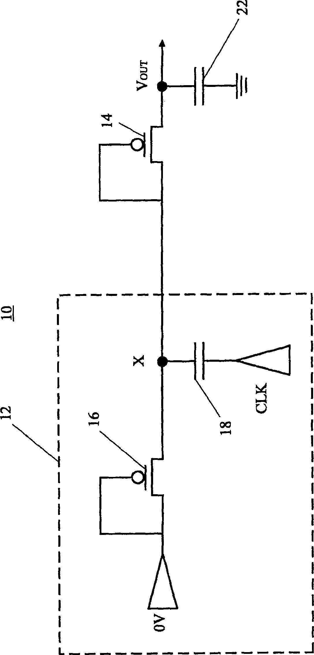
[0027] see Figure 4 , Figure 4 It is a circuit diagram of the first embodiment of the negative voltage converter (converter) 100 of the present invention. The negative voltage converter 100 includes a voltage input circuit 102 and a voltage amplifying circuit 104 . The voltage input circuit 102 can input the DC voltage Vss input from the signal input terminal 1021 to the voltage amplifying circuit 104, and the voltage amplifying circuit 104 can amplify and convert the DC voltage Vss into a required negative DC voltage, and output it from the signal output terminal 1022 .

[0028] The voltage input circuit 102 includes a first transistor M1, a second transistor M2 and a third transistor M3, and the transistors M1-M3 are P-type metal oxide semiconductor transistors. The control terminal of the first transistor M1 is connected to the signal input terminal 1021 of the negative voltage converter 100 , and the signal input terminal 1021 is coupled to a DC supply voltage Vss. A...


PUM


Abstract

A negative voltage converter includes a first transistor, a second transistor, a third transistor, a fourth transistor, a fifth transistor and a sixth transistor. The first terminal and the control terminal of the first transistor are coupled to the signal input terminal. The first terminal of the second transistor is coupled to the signal input terminal, and the control terminal is coupled to the first clock signal and the second terminal of the first transistor. The first end of the third transistor is coupled to the signal input end, and the control end is coupled to the second clock signal and the second end of the second transistor. The first terminal of the fourth transistor is coupled to the second terminal of the third transistor, and the control terminal is coupled to the second terminal of the third transistor. The first terminal of the fifth transistor is coupled to the second terminal of the third transistor, and the control terminal is coupled to the second terminal of the fourth transistor. The first terminal of the sixth transistor is coupled to the second terminal of the third transistor, the second terminal of the sixth transistor is coupled to the signal output terminal, and the control terminal is coupled to the second terminal of the fifth transistor and the first clock signal .

Description

technical field [0001] The invention relates to a negative voltage converter, in particular to a negative voltage converter (Negative voltage converter) composed of a P-type transistor (PMOSFET or P-type Thin Film Transistor). Background technique [0002] refer to figure 1 as well as figure 2 , figure 1 It is a circuit diagram of a negative voltage converter 10 composed of P-type transistors in the prior art, figure 1 The negative voltage converter 10 has a node X. figure 2 This is a case where the voltage of the node X changes as the threshold voltage Vth voltage of the transistor 16 changes. The negative voltage converter 10 is composed of P-type transistors (PMOS or PTFT), and its purpose is to convert the input positive voltage or 0V supply power into the negative DC supply voltage required by circuits or components. The negative voltage converter 10 includes a voltage input circuit 12 and a voltage amplifying circuit 14 . The voltage input circuit 12 includes a...

Claims


Application Information

Patent Timeline
Patent Type & Authority Patents(China)
IPC IPC(8): H02M3/07
Inventor 李昆鸿白承丘吕世香孙文堂
Owner AU OPTRONICS CORP
Why Eureka
Try Eureka