Fuel cell system

a fuel cell and system technology, applied in the field of fuel cell systems, can solve the problems of reducing the output and efficiency of a flat-stack type fuel cell system, affecting the electricity generation reaction that occurs in the unit cell is in turn affected by the temperature of the fuel, so as to reduce the difference of the output characteristics of each unit cell, reduce the temperature difference of the fuel provided, and increase the efficiency of electricity generation

Inactive Publication Date: 2008-09-25
SAMSUNG SDI CO LTD
View PDF3 Cites 0 Cited by
  • Summary
  • Abstract
  • Description
  • Claims
  • Application Information

AI Technical Summary

Benefits of technology

[0011]Some embodiments address one or more of the above-mentioned problems. An aspect provides a fuel cell system including a flat type stack in which a plurality of the unit cells, in which an electricity generating reaction is performed, are arranged on a plane, and the fuel cell system pre-heats the fuel provided from outside the stack for reducing the temperature differences of the fuel provided to each unit cell, and reducing the difference of the output characteristics of each unit cell, thereby increasing the electricity generating efficiency.

Problems solved by technology

On the other hand, the electricity generating reaction that occurs in the unit cell is in turn affected by the temperature of the fuel.
In addition, the output and efficiency of a flat-stack type fuel cell system are reduced due to differences in the output characteristics of each unit cell.

Method used


Image

  • Fuel cell system
  • Fuel cell system
  • Fuel cell system

Examples


Embodiment Construction

[0066]Hereinafter, preferred embodiments will be described in detail with reference to the accompanying drawings to be easily carried out by a person having ordinary skill in the art.

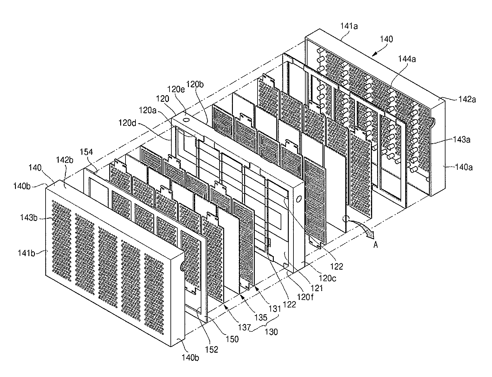
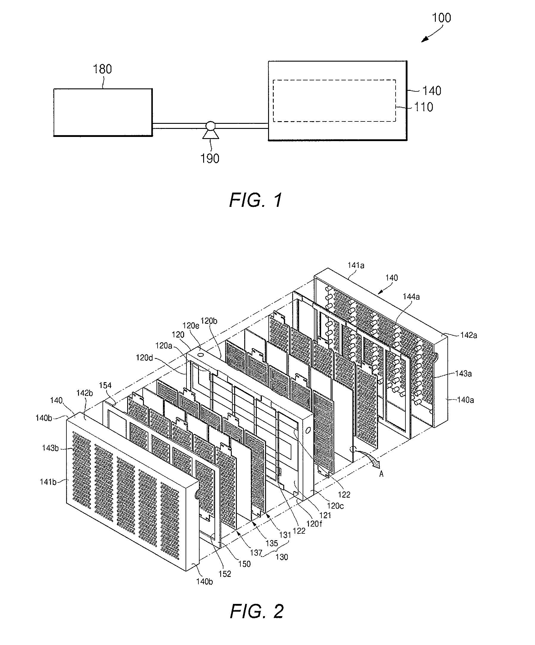
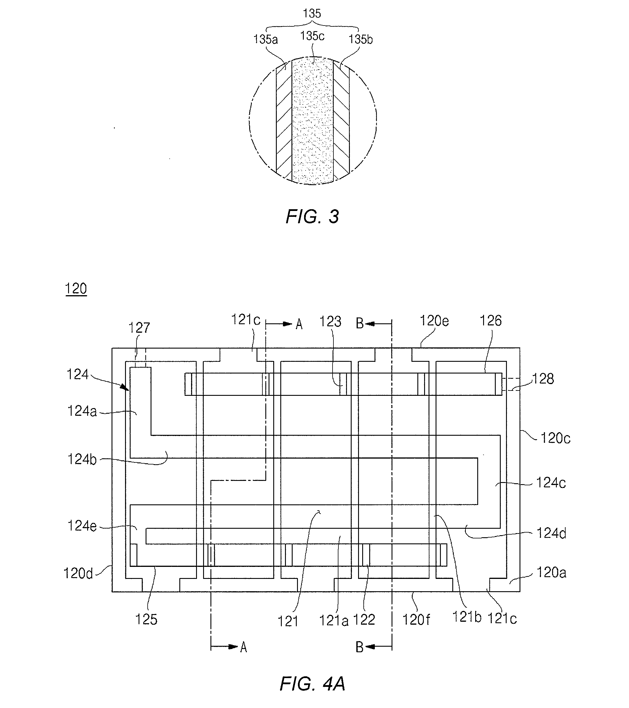
[0067]FIG. 1 is a diagram illustrating a structure of an embodiment of a fuel cell system 100. FIG. 2 is an exploded perspective view illustrating an embodiment of a fuel cell body of a fuel cell system. FIG. 3 is a detailed cross-sectional view of portion A of FIG. 2. FIG. 4A is a front view illustrating a middle plate of the fuel cell body of FIG. 2. FIG. 4B is a sectional view taken along section A-A of FIG. 2. FIG. 4C is a sectional view taken along section B-B of FIG. 2. FIG. 4D is an exploded perspective view illustrating the middle plate of FIG. 4A. FIG. 5 is a front view illustrating an anode part of the fuel cell body of FIG. 2. FIG. 6 is a front view illustrating a cathode part of the fuel cell body of FIG. 2.

[0068]Referring to FIG. 1 to FIG. 6, the fuel cell system 100 according to the illust...


PUM

PropertyMeasurementUnit
shapeaaaaaaaaaa
dimensionaaaaaaaaaa
temperatureaaaaaaaaaa

Abstract

A fuel cell system including a flat type stack in which a plurality of unit cells, in which an electricity generating reaction is performed, are arranged on a plane, and the fuel cell system pre-heats the fuel provided from the outside for reducing the temperature differences of the fuel provided to each unit cell, thereby reduces the differences in the output characteristics of each unit cell, thereby increasing the electricity generating efficiency of the system.

Description

CROSS-REFERENCE TO RELATED APPLICATION[0001]This application claims priority to and the benefit of Korean Patent Application No. 10-2007-0028284, filed on Mar. 22, 2007, the entire contents of which is incorporated herein by reference.BACKGROUND OF THE INVENTION[0002]1. Technical Field[0003]The present disclosure relates generally to a fuel cell system, and in particular, relates to a fuel cell system including a flat-type stack in which a plurality of the unit cells, in which an electricity generating reaction occurs, are arranged on a plane, and in which the fuel is preheated, thereby reducing the temperature differences of the fuel provided to each unit cell, and reducing the difference in the output characteristics of each unit cell, thereby increasing the electrical generating efficiency.[0004]2. Description of the Related Art[0005]A fuel cell is a power generation system that directly converts energy from a chemical reaction between a hydrogen-containing fuel, for example, a h...

Claims


Application Information

Patent Timeline
Patent Type & Authority Applications(United States)
IPC IPC(8): H01M8/02
CPCH01M8/0228H01M8/0232H01M8/0247H01M8/0263H01M8/1011H01M8/2455H01M8/2485Y02E60/50H01M8/2484H01M8/04H01M8/02
Inventor AN, SEONGJINEUN, YEONGCHANCHANG, SEOKRAKROH, GILLTAE
Owner SAMSUNG SDI CO LTD
Why Eureka
Try Eureka