
Wind power turbine

a wind power turbine and turbine blade technology, applied in the direction of machines/engines, renewable energy generation, electric generator control, etc., can solve the problems of reducing the starting torque of the blade is smaller, and the wind power conversion rate is lower when in a fast wind speed, so as to improve the wind power conversion rate, reduce the reverse rotation torque of the drag-type blade, and increase the forward rotation torque

Inactive Publication Date: 2013-10-15
NAT PINGTUNG UNIV OF SCI & TECH
View PDF11 Cites 0 Cited by
  • Summary
  • Abstract
  • Description
  • Claims
  • Application Information

AI Technical Summary

Benefits of technology

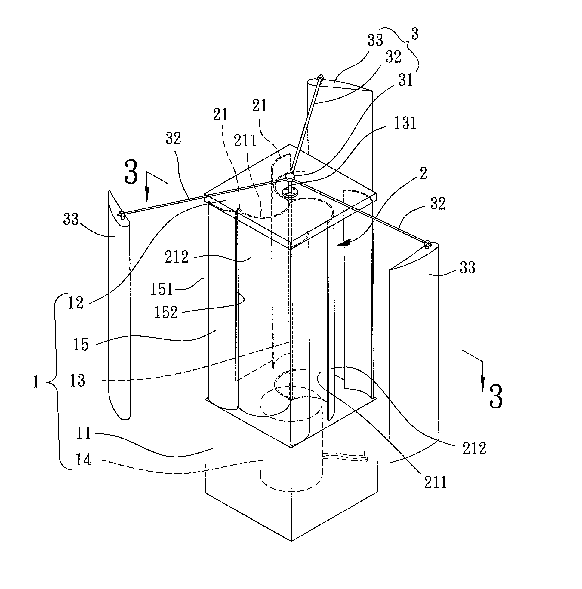
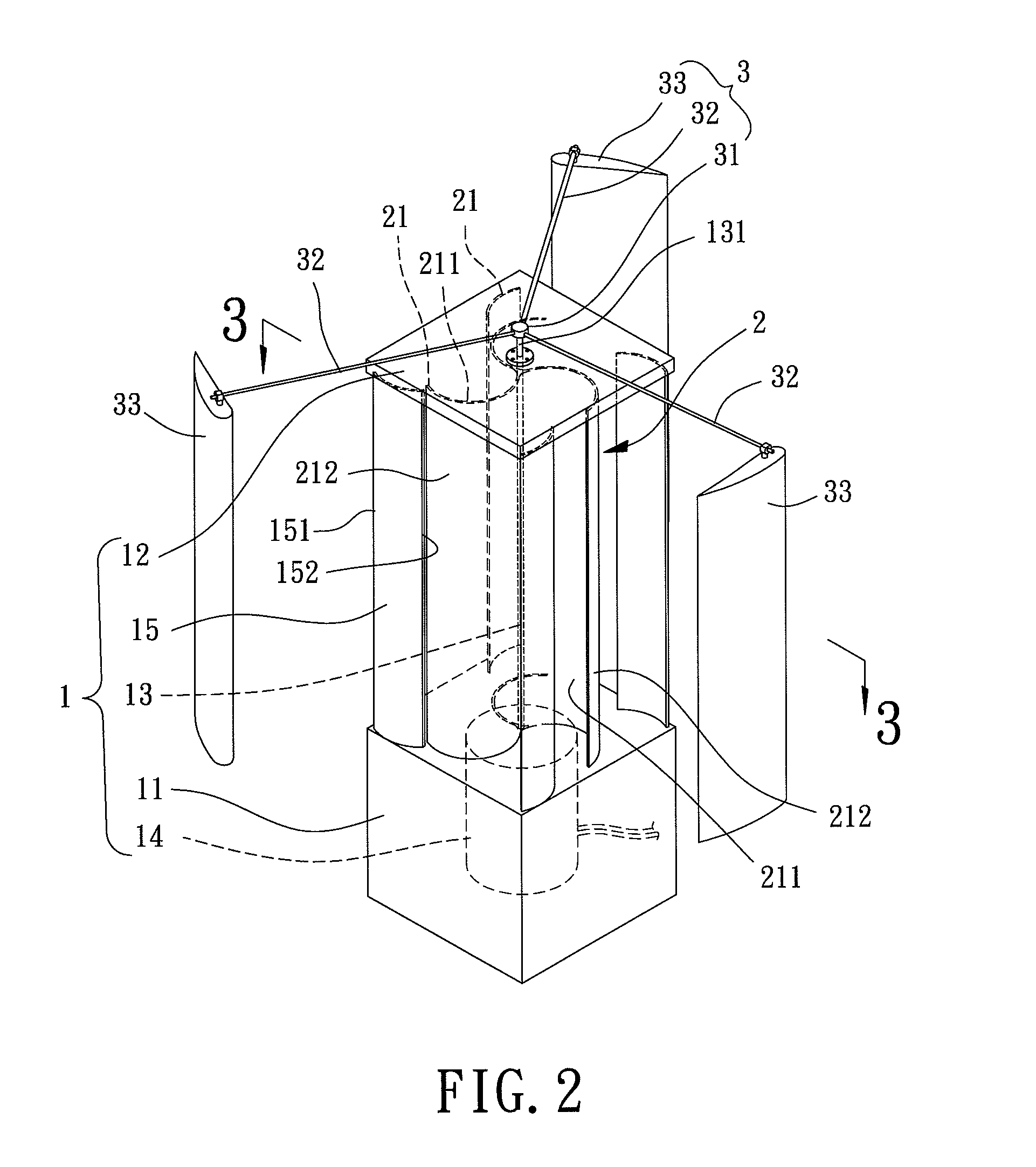
[0008]It is therefore the primary objective of this invention to provide a wind power turbine which improves the wind power conversion rate by using a plurality of air-guiding plates that concentrate the wind on windward faces of drag-type blades for increasing a forward rotation torque and reducing a reversed rotation torque of the drag-type blades.
[0009]It is therefore the other objective of this invention to provide a wind power turbine having a plurality of lift-type blades, each having an asymmetric airfoil cross section. Thus, larger speed difference of wind passing through the inner and outer faces of the lift-type blades is achieved for improving electricity generating efficiency of the wind power turbine.

Problems solved by technology

The drag-type blades have smaller starting torque, which makes it easy to drive the blades to rotate when in a slow wind speed but results in lower wind power conversion rate when in a fast wind speed.
As a result, the reversed rotation torque may offset a portion of the forward rotation torque, leading to a lower wind power conversion rate.
Thus, electricity generation efficiency by wind power is low.

Method used


Image

  • Wind power turbine
  • Wind power turbine
  • Wind power turbine

Examples


Embodiment Construction

[0017]Referring to FIGS. 2 and 3, a wind power turbine including a frame 1, a drag-type fan unit 2 and a lift-type fan unit 3 is disclosed according to a preferred embodiment of the embodiment. The frame 1 includes a shaft 13, with the drag-type fan unit 2 being disposed on an outer circumference of the shaft 13. The shaft 13 has one end connected to an electricity generator 14 having a rotor and a stator (not shown). The lift-type fan unit 3 is disposed around the drag-type fan unit 2 and has one end connected to the other end of the shaft 13, allowing synchronous rotation between the drag-type fan unit 2 and the lift-type fan unit 3. Based on this, electricity power is generated by the electricity generator 14 when the wind blows over the drag-type fan unit 2 and the lift-type fan unit 3.

[0018]The frame 1 further includes a base 11, a top plate 12 and a plurality of air-guiding plates 15. Two ends of the shaft 13 are rotatably coupled with the base 11 and the top plate 12, respect...


PUM


Abstract

A wind power turbine includes a frame, a drag-type fan unit and a lift-type fan unit. The frame has a base, a shaft, an electricity generator and a plurality of air-guiding plates. The air-guiding plates are disposed on the base, and the shaft has one end connected to the electricity generator. The drag-type fan unit has a plurality of drag-type blades coupled to an outer circumference of the shaft. The lift-type fan unit has a plurality of lift-type blades disposed around the drag-type blades. Each of the air-guiding plates has a first side and a second side, and the first and second sides are parallel to the shaft. An air inlet is formed between the first sides of adjacent two of the air-guiding plates, and an air outlet is formed between the second sides of adjacent two of the air-guiding plates. The air inlet is larger than the air outlet.

Description

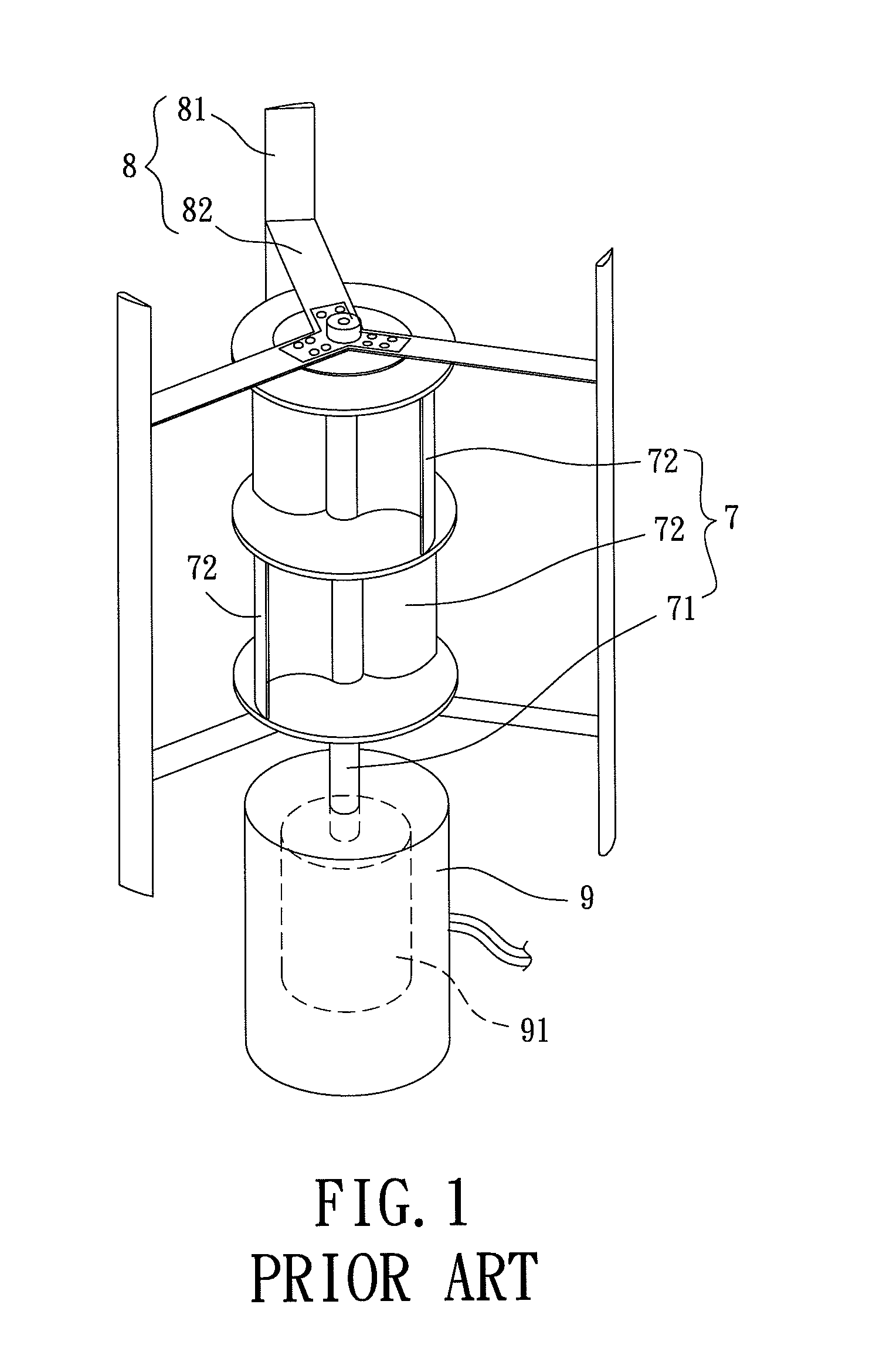
BACKGROUND OF THE INVENTION[0001]1. Field of the Invention[0002]The present invention generally relates to a wind power turbine and, more particularly, to a wind power turbine having both drag-type and lift-type blades for improving electricity generating efficiency thereof.[0003]2. Description of the Related Art[0004]There are two types of blades for wind power turbines based on different operation manners of the blades, such as drag type and lift type. The drag-type blades have smaller starting torque, which makes it easy to drive the blades to rotate when in a slow wind speed but results in lower wind power conversion rate when in a fast wind speed. In contrast, the lift-type blades have larger starting torque when in the slow wind speed, but have better electricity generating efficiency when in the fast wind speed. Thus, based on a combination of both types of blades, the drag-type blades may drive the life-type blades to rotate when in the slow wind speed and the lift-type blad...

Claims


Application Information

Patent Timeline
Patent Type & Authority Patents(United States)
IPC IPC(8): F03D3/02
CPCF03D3/02F03D3/0427F05B2240/213F05B2240/214F05B2240/40Y02E10/74F03D9/25F03D3/0409
Inventor TAI, CHANG-HSIENHSU, UZU-KUEI
Owner NAT PINGTUNG UNIV OF SCI & TECH
Learn More