
Photovoltaic Electrical Connector

a photovoltaic and electrical connector technology, applied in the direction of couplings/cases, coupling device connections, electrical apparatus, etc., can solve the problems of plastic casings that are prone to cracking, large danger, and defect in waterproof effect, so as to prevent any potential displacement or loose connection, effect of reducing the risk of damag

Inactive Publication Date: 2018-05-24
CHANGSHU FRIENDS CONNECTOR TECH
View PDF1 Cites 0 Cited by
  • Summary
  • Abstract
  • Description
  • Claims
  • Application Information

AI Technical Summary

Benefits of technology

The present invention aims to solve issues such as poor waterproofing, insecure snap fitting connections, and inefficient use of copper coils in connectors. The technical effects of this invention include improved waterproofing, better snap fitting connections, and better utilization of copper coils in connectors.

Problems solved by technology

If this connection is not secured there could result in great danger.
However, if the nut is not properly installed, there result defect in waterproof effect.
A Conventional electrical connector has a plastic casing which is prone to crack under extreme external force.
In additional, a conventional electrical connector has a metal terminal typically consist of a copper coil that has high electrical resistance which could reduce electricity generating efficiency.

Method used


Image

  • Photovoltaic Electrical Connector
  • Photovoltaic Electrical Connector
  • Photovoltaic Electrical Connector

Examples


Embodiment Construction

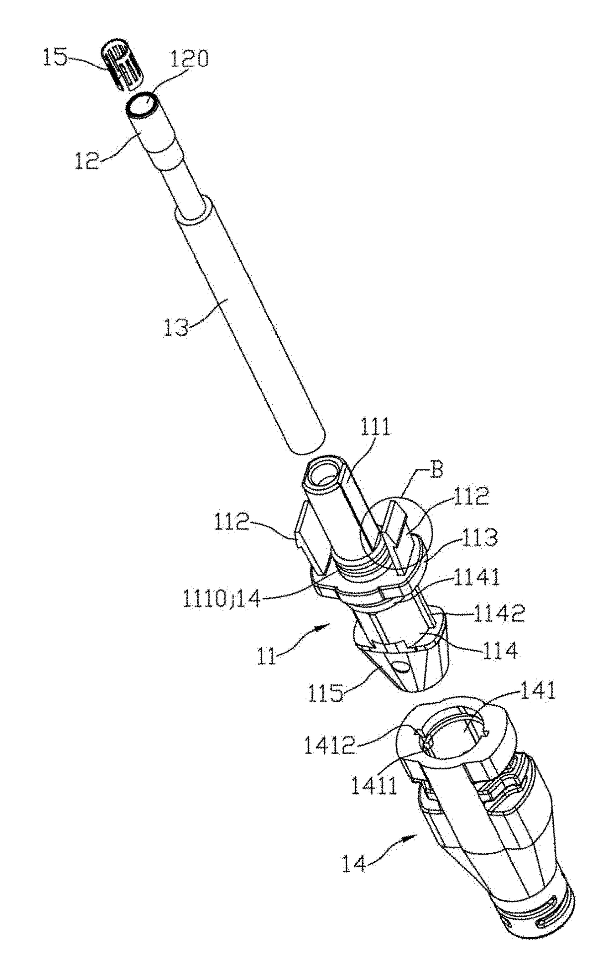
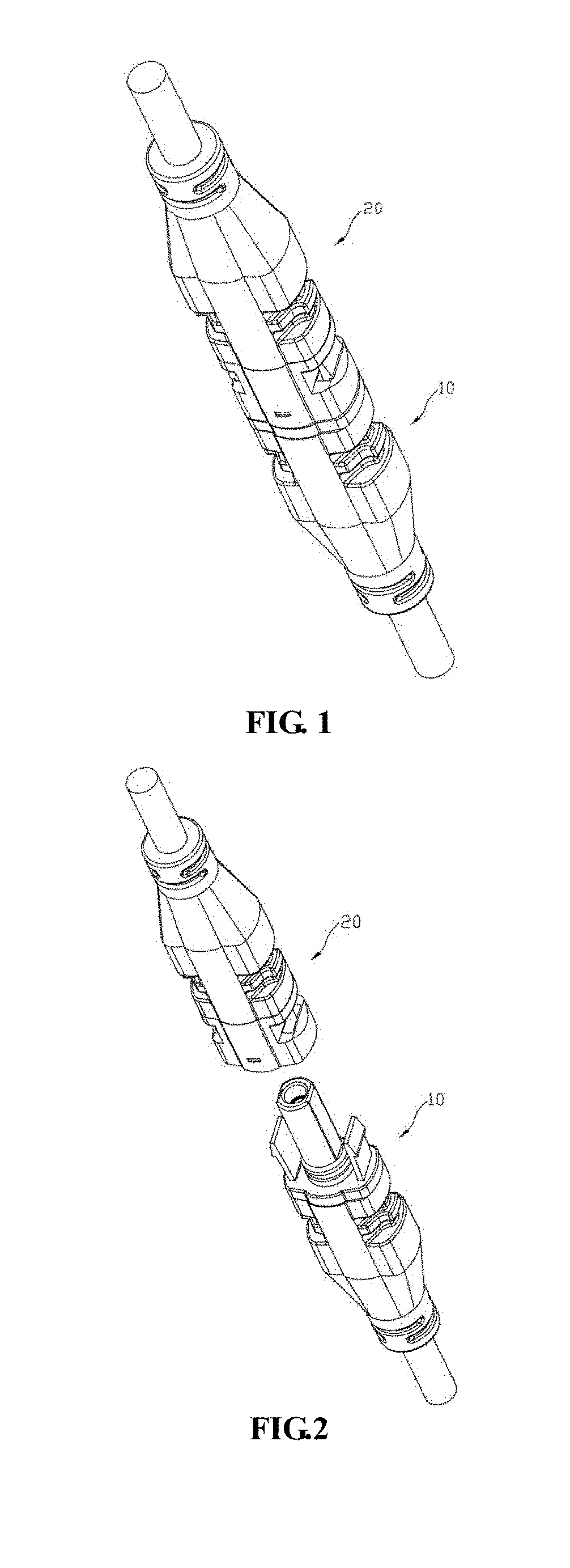
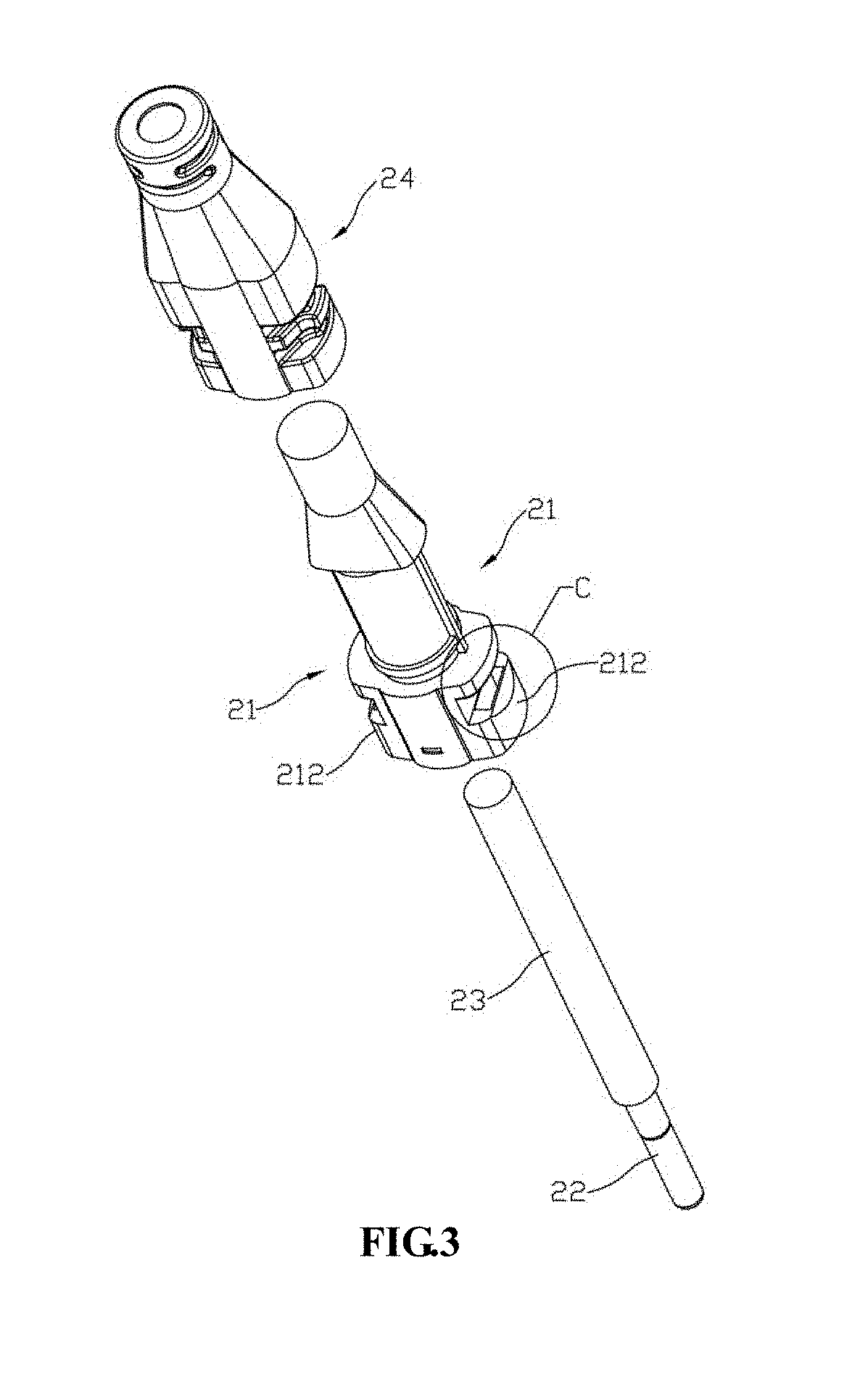
[0029]As shown in FIG. 1, FIG. 2 and FIG. 7, a photovoltaic electrical connector comprising a male plug 10 and a female socket 20.

[0030]In combination with FIG. 4 and FIG. 8, the male plug 10 comprising a first plastic casing 11 and a first lead wire 13 with one end provided with a metal terminal 12 end. The first lead wire 13 with the metal terminal 12 end is position in the first plastic casing 11. One end of the first plastic casing 11 is provided with a plunger 111 and snap fitting arms 112. More specifically, the metal terminal 12 of the first lead wire 13 is position in the plunger 111; and the surface end of the metal terminal 12 is made to form a jack hole 120. The snap fitting arms 112 are positioned around the side of the plunger 111. Wherein, the metal terminal 12 of the first lead wire 13 is in a cylindrical shape formed and obtained by pressing process; one end of the first lead wire 13 and the metal terminal 12 is fixed and connected in the first plastic casing 11 by i...


PUM


Abstract

A photovoltaic electrical connector comprising a male plug and a female socket, each of the male plug and female socket is provide with a plastic casing and a lead wire with one end provided with a metal terminal. The lead wire and the metal terminal are connected and fixed in the plastic casing by injection molding, as such, avoiding the use of snap fitting which could have insecure connection that results in great danger.

Description

BACKGROUND OF INVENTION1. Field of the Invention[0001]The present invention is related to the technic field of solar energy photovoltaic components, more specifically, a photovoltaic electrical connector.2. Description of Related Art[0002]For a conventional electrical connector a metal snap is first fitted into a plastic casing and then a crimped metal terminal wire of a metal terminal is inserted into the plastic casing. The terminal wire is then fasten in the plastic casing by a snap fitting on the metal snap and the metal terminal. If this connection is not secured there could result in great danger. In a conventional electrical connector the outlet end of the lead wire is twisted onto a nut and by tightening the nut to achieve waterproof effect. However, if the nut is not properly installed, there result defect in waterproof effect. A Conventional electrical connector has a plastic casing which is prone to crack under extreme external force. In additional, a conventional electri...

Claims


Application Information

Patent Timeline
Patent Type & Authority Applications(United States)
IPC IPC(8): H01R13/627H01R13/405H01R13/639H01R13/52
CPCH01R13/627H01R13/405H01R13/639H01R13/52H01R13/5219H01R13/6275H02S40/34H02S40/36Y02E10/50
Inventor XU, JIANMING
Owner CHANGSHU FRIENDS CONNECTOR TECH
Learn More