
Medical Device with Cannula Inserter

Inactive Publication Date: 2009-01-08
NOVO NORDISK AS +1
View PDF99 Cites 103 Cited by
  • Summary
  • Abstract
  • Description
  • Claims
  • Application Information

AI Technical Summary

Benefits of technology

[0009]Having regard to the above-identified problems, it is an object of the present invention to provide a skin mountable medical device or system as well as components therefore, which allow such a device or system to be used in a convenient and cost-effective manner, yet allowing safe and reliable treatment of a medical condition.
[0014]Corresponding to a first aspect, the needle is arranged within the cannula such that in the fourth state the distal end of the needle can be positioned within the cannula short of the distal opening. The above arrangement allows the upper leathery layer of the skin to be penetrated with the insertion needle projecting from the cannula. Thereafter the distal ends of the cannula and the needle “shift positions”, e.g. the needle stops and the cannula continues the insertion until the distal end is a short distance in front of the needle end, e.g. 1-5 mm. After this the cannula and the needle together continue the insertion through the relatively soft subcutaneous tissue, the needle providing directional guidance as well as support against kinking, until the cannula is fully inserted. As appears, the combined cannula and needle assembly has a blunt tip when penetrating the sub-cutis thereby causing reduced damage to the subcutaneous tissue. Compared with traditional infusion sets in which the needle penetrates the dermis as well as sub-cutis, less damage can be expected. Once the cannula is fully inserted, the needle is retracted.
[0015]To provide the relative motions between the cannula, the needle and the housing, an exemplary embodiment comprises an inserter assembly for moving the cannula and the insertion needle between the different states as defined above. The inserter assembly comprises the cannula, an inserter for moving the cannula, the needle, and a needle holder attached to the needle. The inserter assembly has (a) an initial state in which the needle holder is locked to the inserter in an initial position with the distal end of the needle projecting from the distal opening of the cannula, (b) an intermediate state in which the needle holder is locked to the inserter in an intermediate position with the distal end of the needle positioned within the cannula short of the distal opening, and optionally (c) a retracted state in which the needle is retracted from the portion of the cannula extending from the housing. This arrangement allows the inserter to function as the primary vehicle for moving the cannula and the needle, the “shift” between the initial and the intermediate state allowing the relative movement between the cannula and needle after the initial insertion through the outer layer of the skin.
[0017]To prevent displacement of the inserted cannula, the fully extended cannula may be locked in place relative to the housing. For example, in case the inserter is left in place and only the needle is withdrawn, locking means (e.g. barbs or hooks) may be provided between the housing and the inserter. Alternatively, the cannula may be attached to a cannula which can be moved by the inserter from a retracted to a fully extended position, the cannula holder and the housing comprising cooperating fastening means for locking the cannula in its extended position, this allowing the inserter to be withdrawn after insertion.
[0020]The medical device may be provided with a flexible sheet member with a lower surface adapted to be arranged on a skin surface of a subject (e.g. comprising an adhesive), and an upper surface to which the first housing portion is arranged. In this way the cannula can be securely held in place after insertion.
[0032]To reduce the likelihood of transcutaneous device injuries, the distal end of the transcutaneous device may be moveable between the extended position in which the end projects relative to the mounting surface, and a retracted position in which the end is retracted relative to the mounting surface.

Problems solved by technology

The first class comprises infusion pumps which are relatively expensive pumps intended for 3-4 years use, for which reason the initial cost for such a pump often is a barrier to this type of therapy.
When a needle enters the subcutaneous tissue, the cutting edge will cause lesions to this tissue; cells are punctured, the fine blood vessels are damaged and nerve connections are cut, causing hemorrhage and trauma to the patient.
Further, such hemorrhage triggers an immune reaction in the tissue, causing the chemical environment in the skin at the insertion site to change.
This can influence the effect of the injected substance, which of course is undesirable.
This is especially an issue for obliquely inserted soft cannulas as these are normally inserted with a long travel to reach the desired depth of insertion in the subcutaneous space.

Method used


Image

  • Medical Device with Cannula Inserter
  • Medical Device with Cannula Inserter
  • Medical Device with Cannula Inserter

Examples


Embodiment Construction

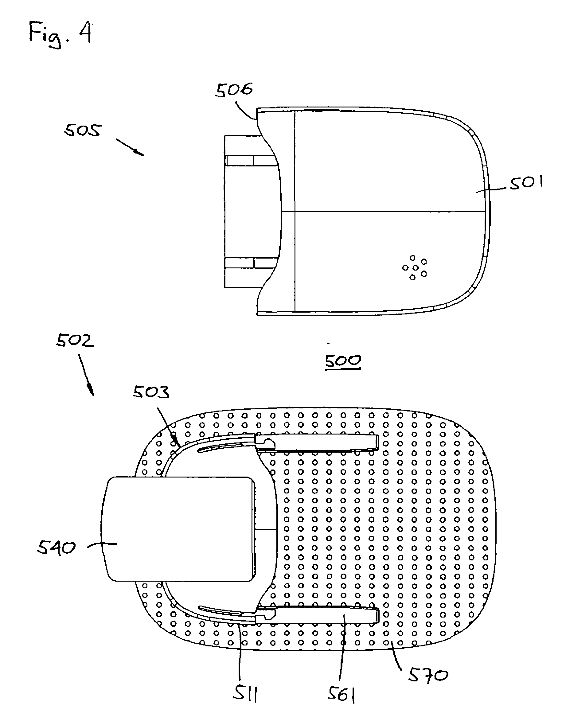
[0060]When in the following terms such as “upper” and “lower”, “right” and “left”, “horizontal” and “vertical” or similar relative expressions are used, these only refer to the appended figures and not to an actual situation of use. The shown figures are schematic representations for which reason the configuration of the different structures as well as there relative dimensions are intended to serve illustrative purposes only.

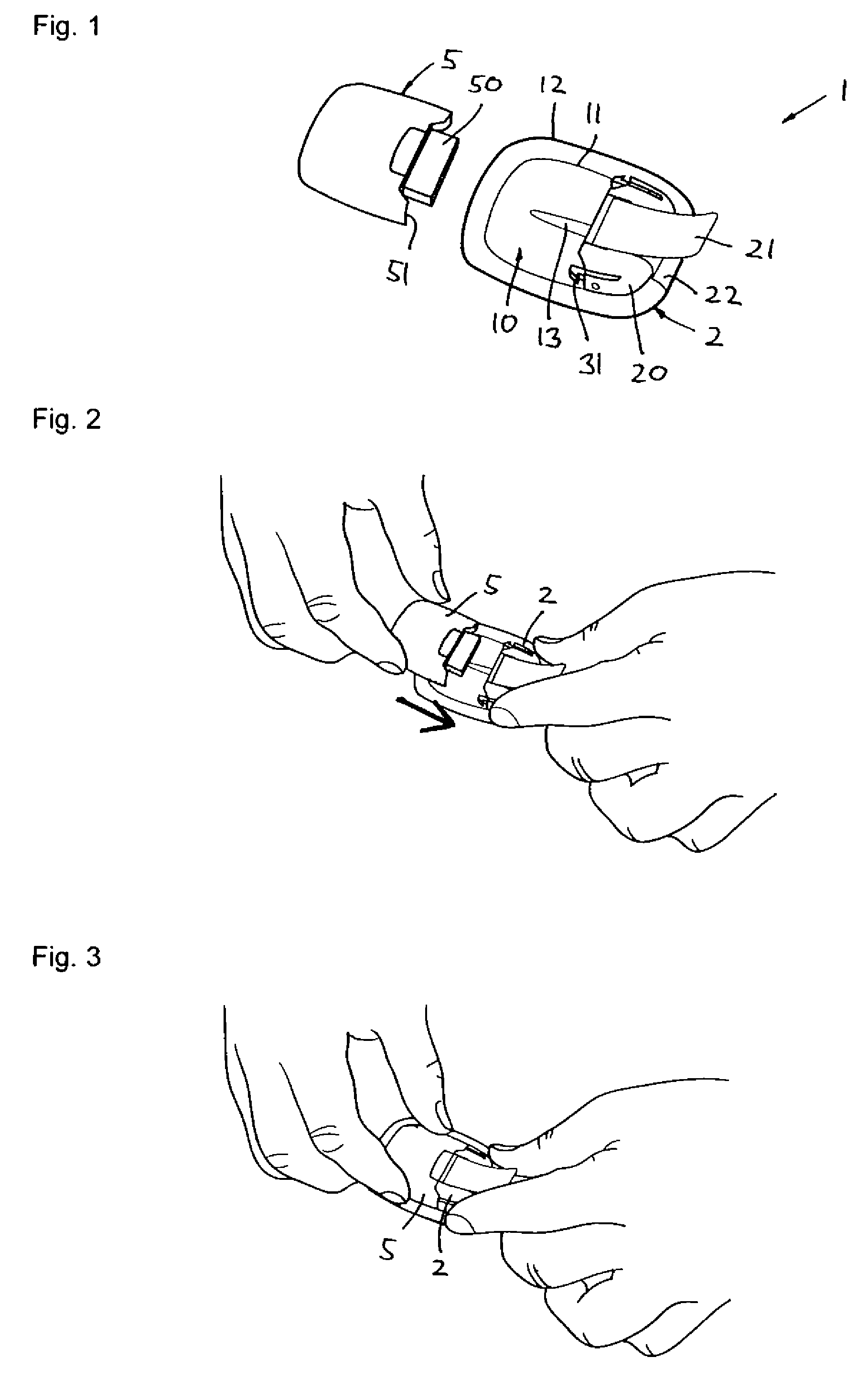
[0061]Firstly, with reference to FIGS. 1-3 an embodiment of a medical device for drug delivery will be described focusing primarily on the directly user-oriented features. The transcutaneous device unit 2 comprises a transcutaneous device in the form of a hollow infusion device, e.g. a needle or soft cannula, and will thus in the following be termed a needle unit, however, the needle may be replaced with any desirable transcutaneous device suitable for delivery of a fluid drug or for sensing a body parameter.

[0062]More specifically, FIG. 1 shows a perspective v...


PUM


Abstract

A medical device is provided comprising a cannula (771, 861) having a distal end portion adapted to be arranged through the skin of the subject and having a distal opening, and a needle (761, 861) arranged coaxially with and being axially moveable relative to the cannula, the needle comprising a pointed distal end, wherein the device is adapted for advancing the cannula with the distal end of the needle projecting there from through the dermis of the subject, and further advancing the cannula into the subcutis of the subject with the distal end of the cannula projecting relative to the needle.

Description

[0001]The present invention generally relates to a device which is adapted for application to a skin surface of a subject and comprises a cannula in combination with an insertion needle, the insertion needle serving as an insertion aid for the cannula which typically is more flexible than the insertion needle. In embodiments of the invention the cannula may be replaced with a sensor.BACKGROUND OF THE INVENTION[0002]In the disclosure of the present invention reference is mostly made to the treatment of diabetes by injection or infusion of insulin, however, this is only an exemplary use of the present invention.[0003]Portable drug delivery devices for delivering a drug to a patient are well known and generally comprise a reservoir adapted to contain a liquid drug and having an outlet in fluid communication with a hollow infusion needle, as well as expelling means for expelling a drug out of the reservoir and through the skin of the subject via the hollow needle. Such devices are often...

Claims


Application Information

Patent Timeline
IPC IPC(8): A61M5/20
CPCA61M5/14248A61M5/158A61M2005/14252A61M2005/1587A61M2005/1581A61M2005/1585A61M2005/1426
Inventor AHM, THORKILDTEISEN-SIMONY, CLAUDERORVIG, SIMON
Owner NOVO NORDISK AS
Learn More