High voltage interlock switch

a high-voltage interlock switch and switch technology, applied in the direction of electrical devices, coupling device connections, transportation and packaging, etc., can solve the problems of time delay of a person attempting to access a component or subsystem, time required to remove the bolt, delay the access to the protected high-voltage area, etc., to prevent exposure to danger

Active Publication Date: 2006-08-01
GM GLOBAL TECH OPERATIONS LLC
View PDF8 Cites 110 Cited by
  • Summary
  • Abstract
  • Description
  • Claims
  • Application Information

AI Technical Summary

Benefits of technology

[0005]The purpose of a high-voltage interlock loop (‘HVIL’) system is to prevent exposure to the danger of contact with elements of high-power electrical devices and components. The device of this invention has two functions. First, it acts as a switch in a circuit loop consisting of any number of similar switches, any one of which, when opened, interrupts the flow of current through the entire loop. This opening of the circuit is a signal to a control device to take action to de-energize the high voltage power system. Second, because of its physical shape and design, it provides a time delay to a person attempting to access a component or subsystem of the high-voltage system. This invention includes a two-part device comprising a connector and shroud for a hold-down fastener of an access cover of the high-voltage system. To gain access to the fastener, one must remove the shroud of the two-part device from the connector. Separation of the two halves of the connector opens the circuit and exposes the access fastener. The time required to remove the bolt delays access to the protected high-voltage area. This delay may be increased by adding to the length of the bolt, and using a fastener that requires a unique tool to remove it. This device has a construction and material content similar to many common plastic overmolded electrical components. The connector preferably conforms to a current automotive industry standard connector system.

Problems solved by technology

Second, because of its physical shape and design, it provides a time delay to a person attempting to access a component or subsystem of the high-voltage system.
The time required to remove the bolt delays access to the protected high-voltage area.

Method used


Image

  • High voltage interlock switch
  • High voltage interlock switch
  • High voltage interlock switch

Examples


Embodiment Construction

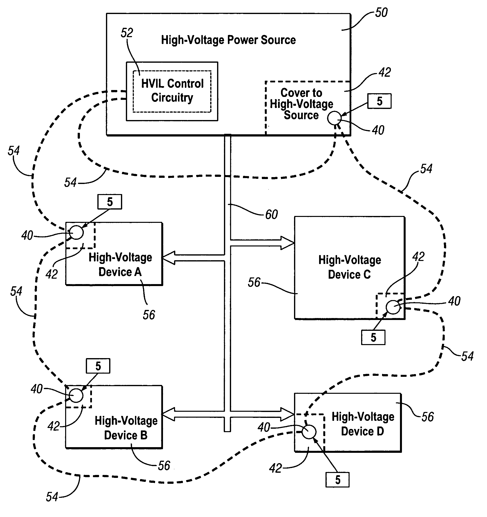
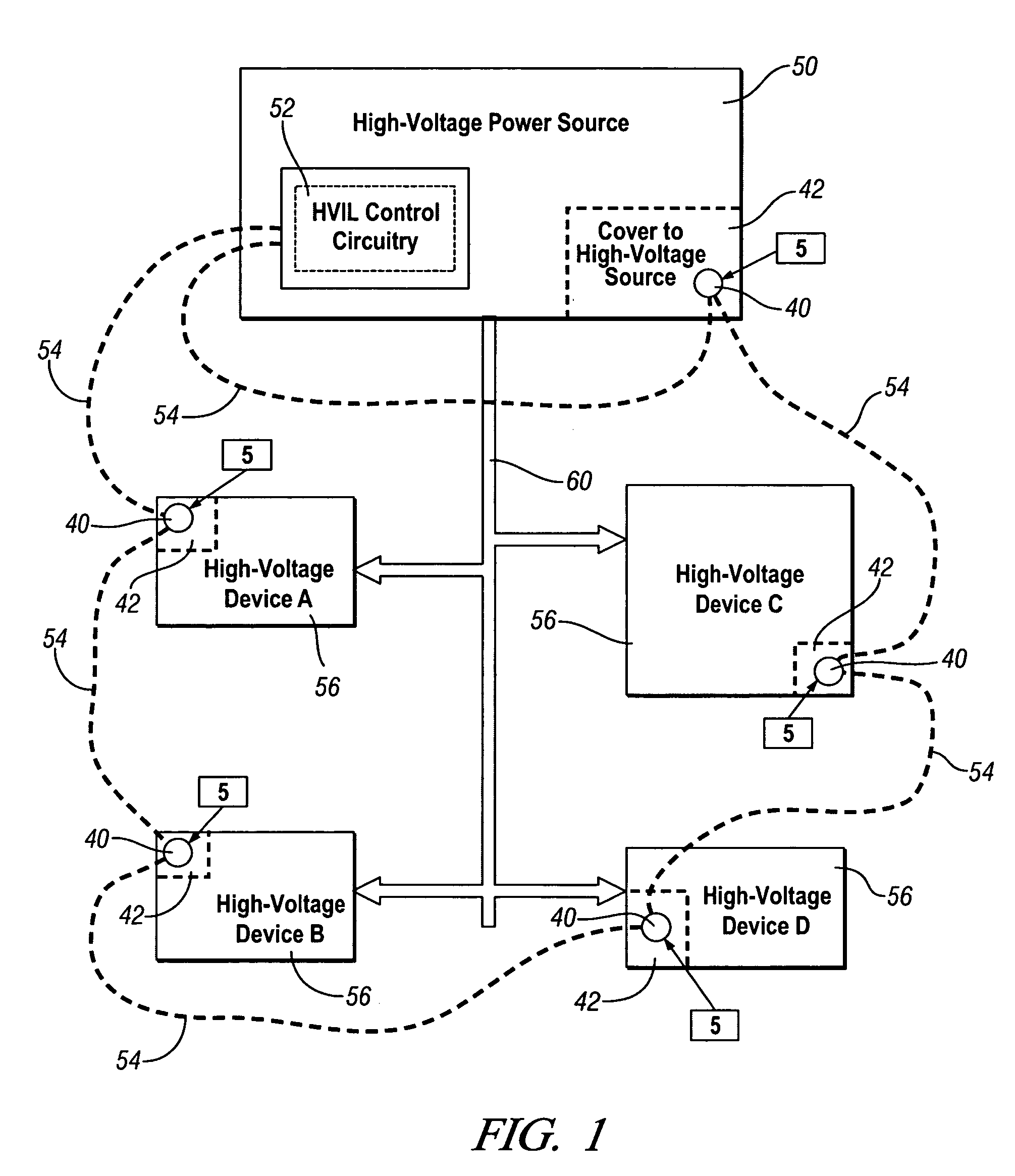
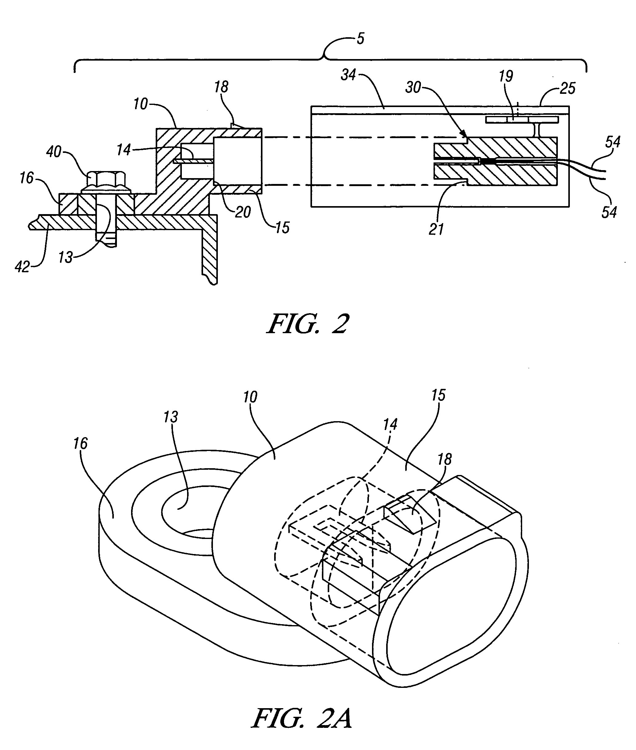
[0026]Referring now to the drawings, wherein the showings are for the purpose of illustrating the invention only and not for the purpose of limiting the same, FIG. 1 shows a schematic high-voltage interlock loop circuit which has been constructed in accordance with an embodiment of the present invention.

[0027]The exemplary high-voltage interlock loop circuit comprises a high-voltage power source 50, including a high-voltage interlock loop (‘HVIL’) control circuit 52. The high-voltage power source 50 distributes electrical power to a plurality of high voltage devices 56 via one or more electrical cables 60, each capable of carrying sufficient amount of electrical energy to meet needs of the specific high voltage device 56. The HVIL control circuit 52 is serially electrically connected to a plurality of HVIL switch devices 5 using a plurality of wire cables 54. The high-voltage interlock loop circuit is preferably created by the plurality of HVIL switch devices 5 and wire cables 54 co...


PUM


Abstract

A switch device for assembly with a fastener securing an access cover to a high voltage storage device includes a switch connector device connectable to a shroud. The switch connector includes a flange with a bolt hole through which a fastener passes and a first connector having a shorting bar. The shroud includes a second connector with first and second wire cables, mateable to the first connector. The switch device has open and closed positions. In closed position, the shroud is mated to the switch connector device, and conducts electrical signals between the first and second wire cables. The shroud substantially completely obstructs operative access to the fastener. In open position, the shroud is sufficiently unmated from the switch connector device to permit operative tool access to the fastener. The first connector is disconnected from the second connector when in the open position.

Description

TECHNICAL FIELD[0001]This invention pertains generally to voltage interlock systems, and more specifically to a high voltage interlock switch system.BACKGROUND OF THE INVENTION[0002]Manufacturers of systems employing circuits which transmit electrical power, including modern vehicle propulsion systems, are generally aware that it is not desirable for a service technician or other individuals to have physical contact with components or systems that are at elevated voltage levels. Typical high-voltage power systems employ energy storage devices requiring a certain amount of time to discharge stored electrical power prior to access. Examples of such energy storage devices include batteries, inductors, and capacitors. The potential energy of any such device must be discharged or dissipated before contact may safely occur. The process of discharging electrical energy takes a finite amount of time. To prevent premature physical contact, such systems often employ barriers to access, such a...

Claims


Application Information

Patent Timeline
Patent Type & Authority Patents(United States)
IPC IPC(8): H01H21/54
CPCB60L3/0069B60L3/04H01R13/447Y10S439/923H01R13/7031H01R31/08H01R13/6397
Inventor BOWES, CHRISTOPHER J.HOWENSTEIN, MICHAEL J.KISIELEWSKI, TED R.
Owner GM GLOBAL TECH OPERATIONS LLC
Why Eureka
Try Eureka