System and method to pre-ignition in an internal combustion engine

a technology of internal combustion engine and pre-ignition, which is applied in the direction of electrical control, process and machine control, instruments, etc., can solve the problems of limited mixing time and knock, and achieve the effects of reducing the density of air in the cylinder, and reducing the pre-ignition

Active Publication Date: 2007-02-20
FORD GLOBAL TECH LLC
View PDF9 Cites 168 Cited by
  • Summary
  • Abstract
  • Description
  • Claims
  • Application Information

AI Technical Summary

Benefits of technology

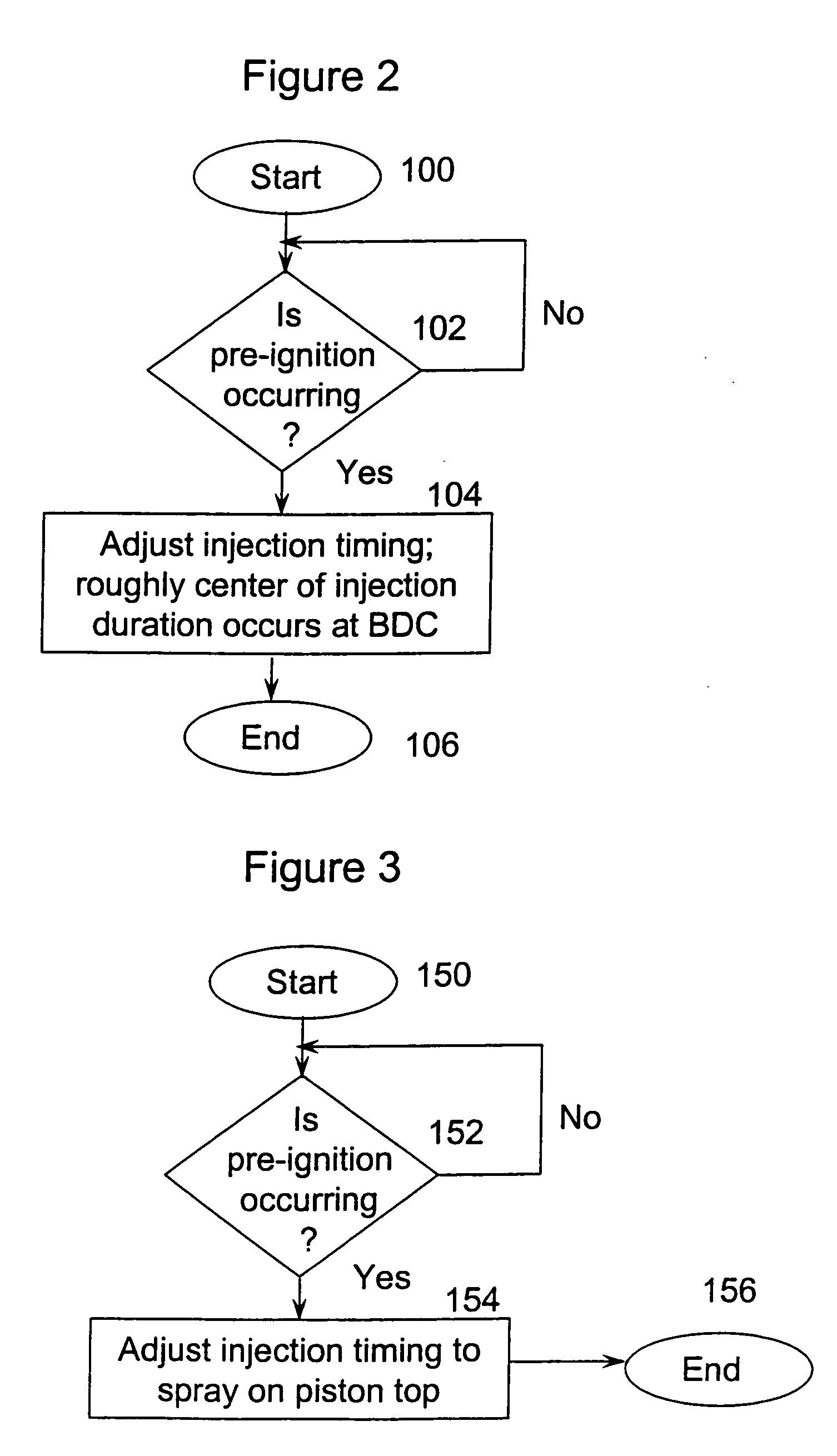
[0004]The inventor of the present invention recognizes two strategies to mitigate pre-ignition. In one method, fuel is injected into the cylinder to avoid contact with the surface as much as possible. This is accomplished by injecting the fuel when the piston is at its farthest position from the fuel injector, i.e., BDC. As injection occurs over a range of piston positions, the fuel injection begins prior to the piston reaching BDC and concludes after the piston passes BDC, approximately centering the injection duration at BDC. This provides the least opportunity for the fuel to hit the piston's surface as well as bouncing off the piston top and spraying onto other hot combustion chamber surfaces such as exhaust valves or spark plug tips. Further, the fuel is predominantly in contact with the air, thus, absorbing the energy for its phase change from liquid to gaseous from the air. Cooling of the charge provides two advantages: reducing the density of the air in the cylinder allowing more air to be inducted and thus more power produced in the cylinder; and prevention of endgas autoignition or knock. In a second method, fuel is intentionally injected onto the piston top. The evaporation of the fuel from the piston top provides cooling of that surface and mitigates pre-ignition. To spray onto the piston, fuel is injected early on the intake stroke, a downward stroke of the piston. Alternatively, fuel is injected late on the compression stroke, an upward stroke of the piston. Injecting during the intake stroke allows sufficient time for air-fuel mixing; whereas, mixing time is limited when injection occurs during compression.

Problems solved by technology

Injecting during the intake stroke allows sufficient time for air-fuel mixing; whereas, mixing time is limited when injection occurs during compression.
However, a problem arises when the alcohol fuel is pre-igniting.
However, if the gasoline fuel is used, knock occurs.

Method used


Image

  • System and method to pre-ignition in an internal combustion engine
  • System and method to pre-ignition in an internal combustion engine
  • System and method to pre-ignition in an internal combustion engine

Examples


Embodiment Construction

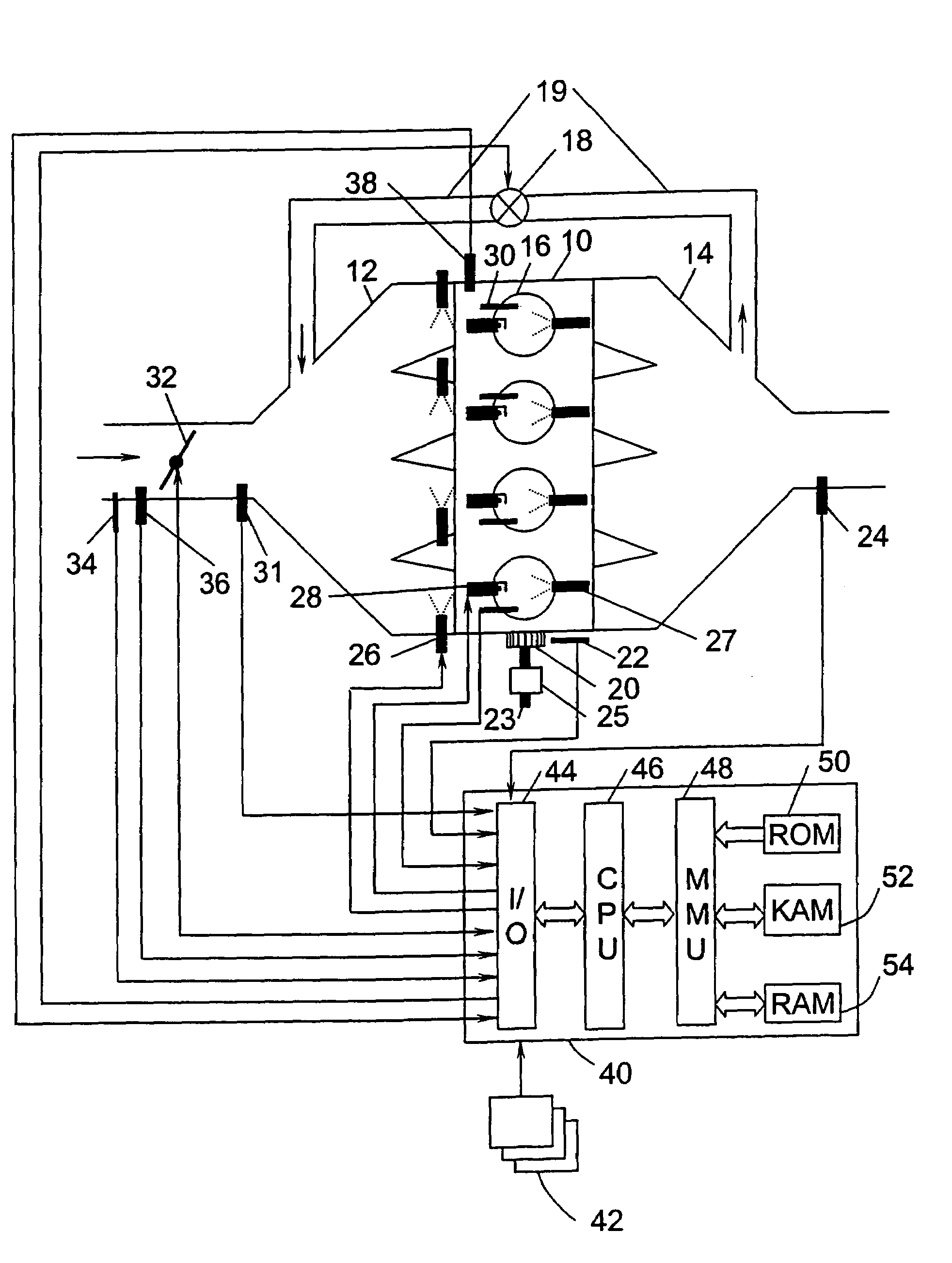
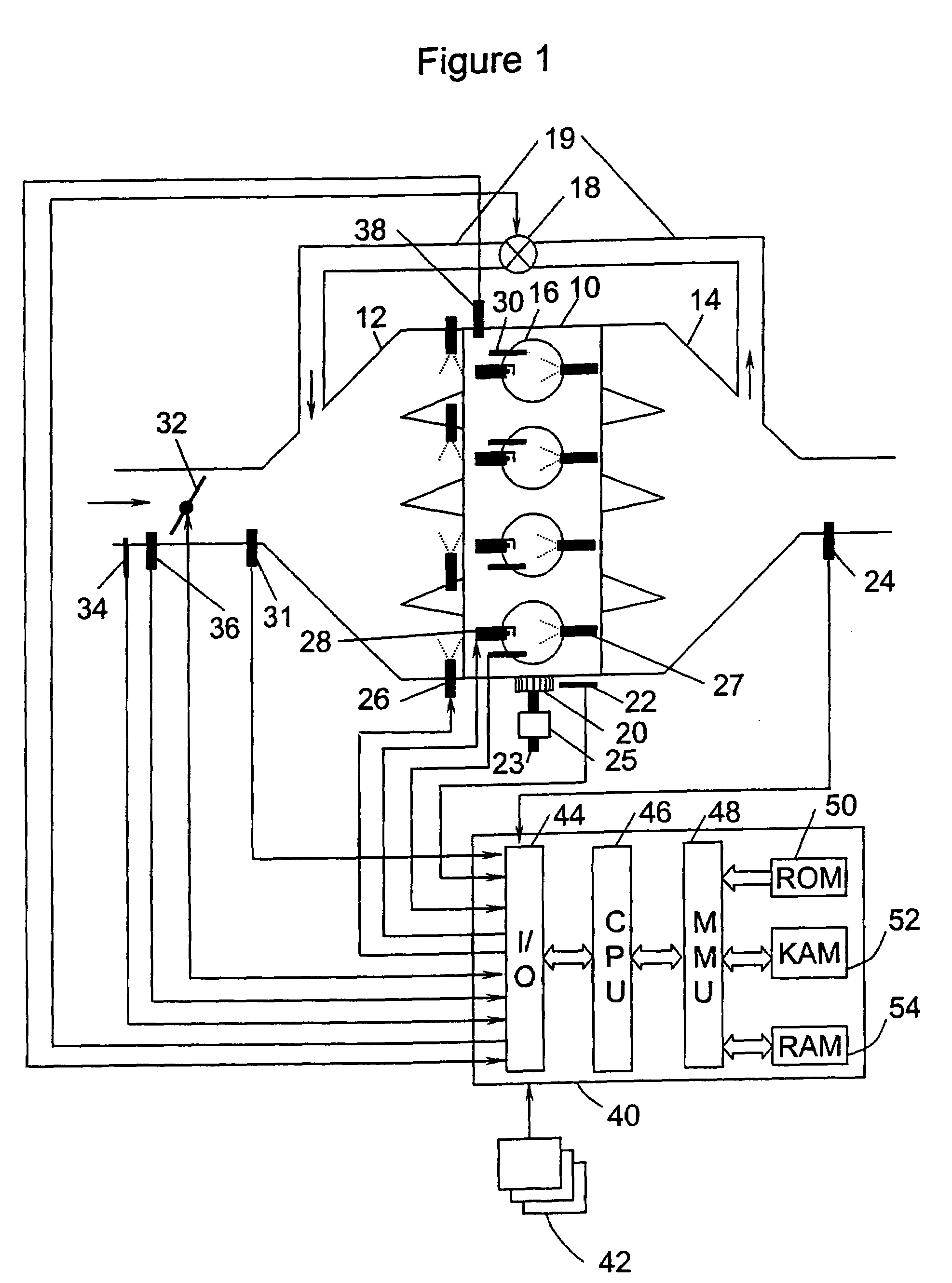
[0010]A 4-cylinder internal combustion engine 10 is shown, by way of example, in FIG. 1. Engine 10 is supplied air through intake manifold 12 and discharges spent gases through exhaust manifold 14. An intake duct upstream of the intake manifold 12 contains a throttle valve 32 which, when actuated, controls the amount of airflow to engine 10. Sensors 34 and 36 installed in intake manifold 12 measure air temperature and mass air flow (MAF), respectively. Sensor 31, located in intake manifold 14 downstream of throttle valve 32, is a manifold absolute pressure (MAP) sensor. A partially closed throttle valve 32 causes a pressure depression in intake manifold 12. When a pressure depression exists in intake manifold 12, exhaust gases are caused to flow through exhaust gas recirculation (EGR) duct 19, which connects exhaust manifold 14 to intake manifold 12. Within EGR duct 19 is EGR valve 18, which is actuated to control EGR flow. Fuel is supplied to engine 10 by port fuel injectors 26, by...


PUM


Abstract

An engine system and method are disclosed for controlling pre-ignition of an alcohol fuel. In one embodiment, the fuel injection timing is adjusted to cause the fuel to avoid combustion chamber surfaces. In another embodiment, the fuel injection timing is adjusted to spray the fuel directly onto the piston surface to cool the piston. Also disclosed is a cylinder cleaning cycle in which engine knock is purposely caused for one to hundreds of engine cycles by adjusting the fuel content away from alcohol toward gasoline. Further measures to cause knock which are disclosed: adjusting spark timing, intake boost, exhaust gas fraction in the cylinder, cam timing, and transmission gear ratio.

Description

FIELD OF INVENTION[0001]The present invention relates to controlling pre-ignition in internal combustion engines.BACKGROUND OF THE INVENTION[0002]Alcohol fuels are known to have a high octane number, which inhibits autoignition (also known as knock; knock is self ignition of end gases ahead of the flame front occurring after spark firing) in spark-ignited internal combustion engines. This allows an internal combustion engine to be operated at a higher compression ratio and / or a higher level of pressure charging in the intake system. However, alcohol fuels are prone to pre-ignition, which is a combustion phenomenon occurring prior to spark plug firing. It is believed to be a surface phenomenon where the fuel comes in contact with a hot spot in the combustion chamber, such as the spark plug tip, a bit of carbon deposit, the piston top, and exhaust valve, and initiates a flame front. This can lead to damage of the engine because it can become a runaway problem. That is, when pre-igniti...

Claims


Application Information

Patent Timeline
Patent Type & Authority Patents(United States)
IPC IPC(8): F02M43/00F02M43/04
CPCF02D35/027F02D41/0025F02D41/3094F02D41/345F02M69/044F02M43/04Y02T10/44F02M63/0225F02M2200/95Y02T10/40
Inventor BREHOB, DIANA D.
Owner FORD GLOBAL TECH LLC
Why Eureka
Try Eureka