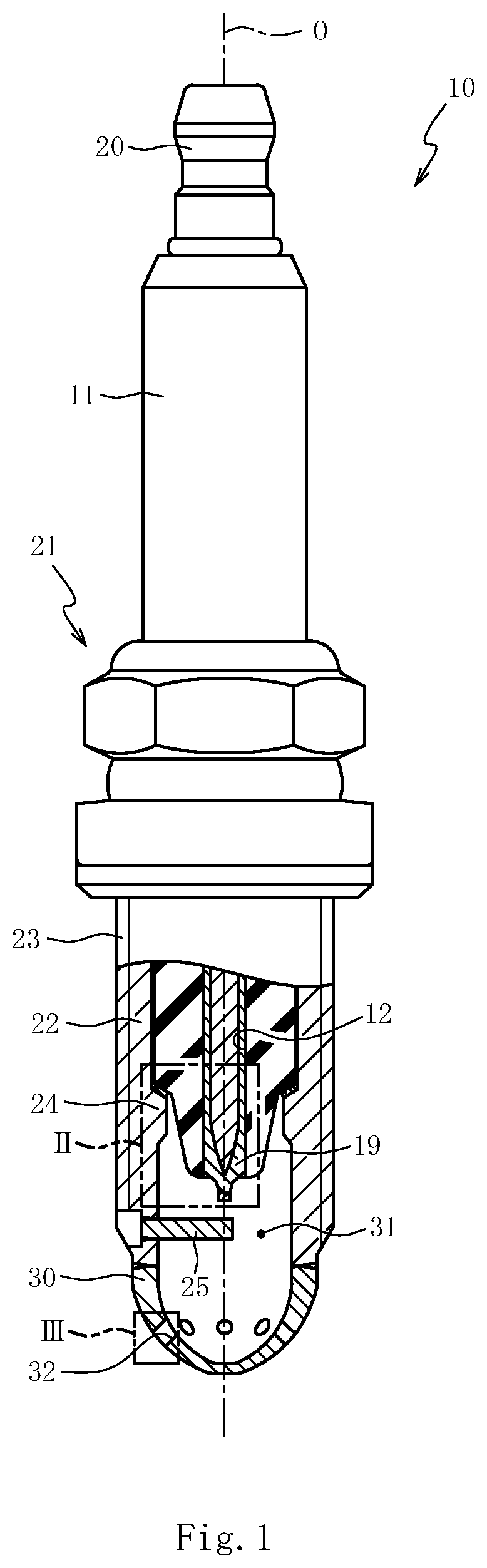
Spark plug

a technology of spark plugs and plugs, which is applied in the manufacture of spark plugs, spark plugs, electrical equipment, etc., can solve the problems that the cap through the orifices can be a spark causing pre-ignition, and achieve the effects of reducing the surface area of the heated front end portion, enhancing the fluidity of the fuel gas, and reducing the overheating of the front end portion

Active Publication Date: 2022-09-15
NGK SPARK PLUG CO LTD
View PDF7 Cites 1 Cited by
  • Summary
  • Abstract
  • Description
  • Claims
  • Application Information

AI Technical Summary

Benefits of technology

[0004]The present invention is made to address the abovementioned problem, and an object of the present invention is to provide a spark plug that can reduce pre-ignition of fuel gas that has flowed into a cap.

Problems solved by technology

In existing technologies, when the temperature inside the cap rises and the insulator is excessively heated, the fuel gas that has flowed into the cap through the orifices can be a spark causing pre-ignition.

Method used


Image

  • Spark plug
  • Spark plug
  • Spark plug

Examples


examples

[0041]The present invention will be described further in detail with the following example, but the present invention is not limited to this example.

(Sample Fabrication)

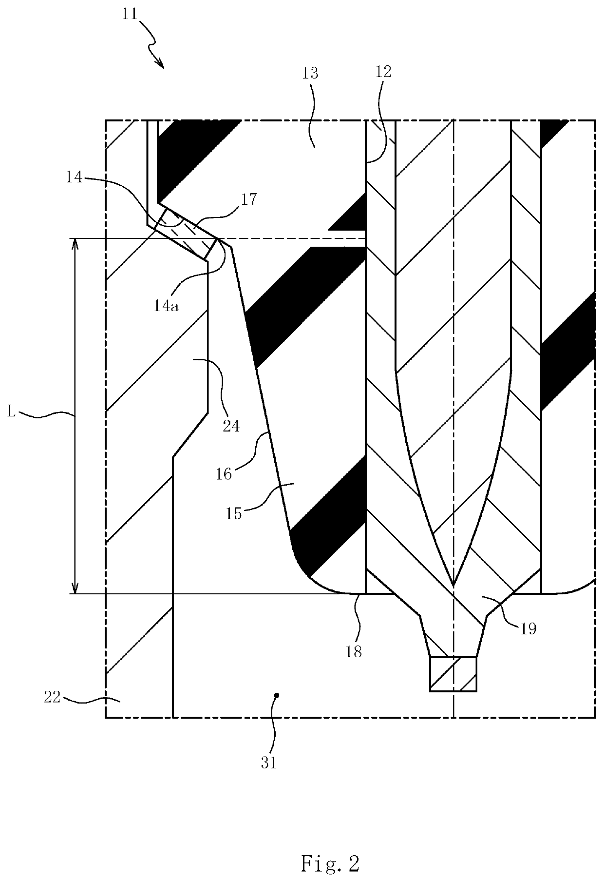
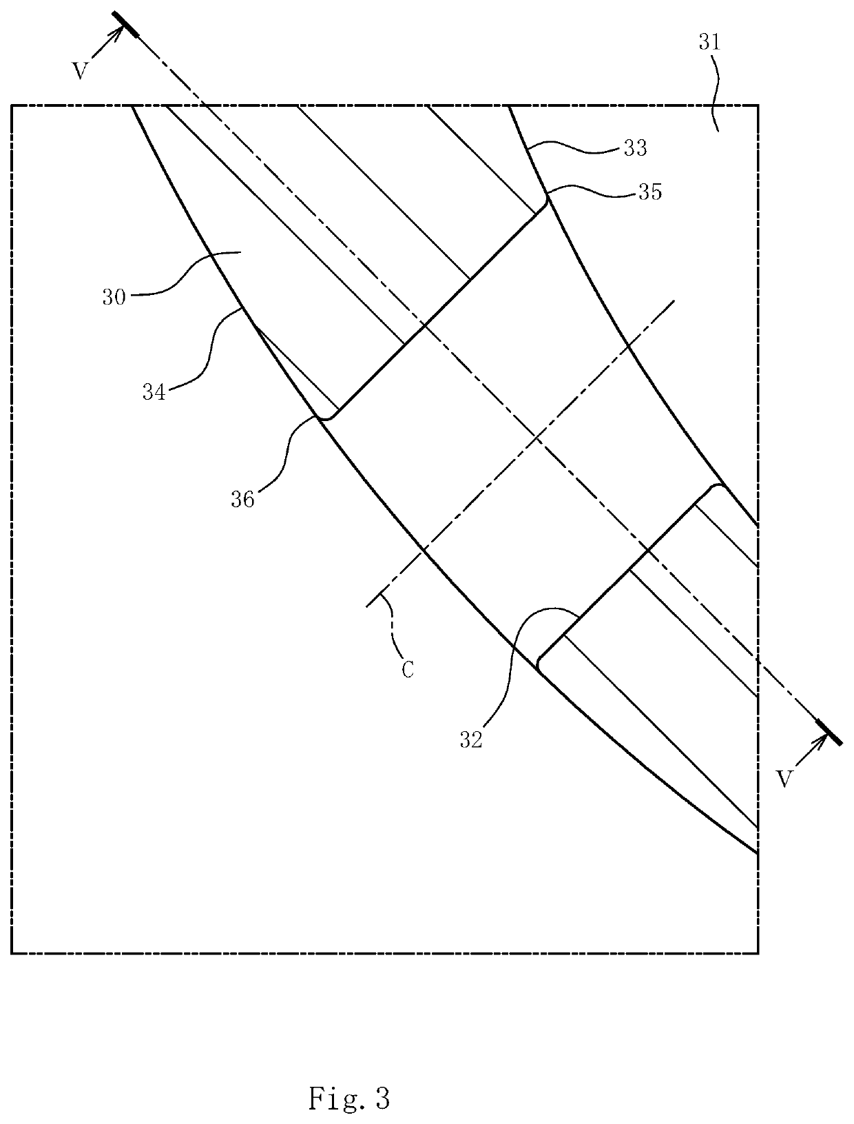
[0042]Similarly to the spark plug 10 according to an embodiment, a tester fabricated samples Nos. 1 to 11 as shown in Table 1. The samples Nos. 1 to 11 differ in length L (mm) of the front end portion 15 of the insulator 11, number obtained by subtracting “the sum of the number of one or more largest orifices 37 and the number of large orifices 38” from “the sum of the number of small orifices 39 and the number of one or more smallest orifices 40”, rate (%) of the minimum cross-sectional area of the largest orifice 37 to the minimum cross-sectional area of the smallest orifice 40, and as to whether all the orifices 32 and the straight lines 42 cross each other in the projection 41. The samples Nos. 1 to 11 have the same quantity, dimensions, or shapes other than the above portions. The samples Nos. 1 to 11 each have ...


PUM


Abstract

A spark plug includes a tubular metal shell; an insulator including a locking portion locked onto the metal shell; and a cap disposed at a front end side of the metal shell, the cap having a plurality of orifices. The plurality of orifices include orifices with different cross-sectional areas. A sum of the number of one or more largest orifices and the number of one or more large orifices that have a cross-sectional area of larger than or equal to 90% of the one or more largest orifices is smaller than the number of orifices that are other than the one or more largest orifices and the one or more large orifices. A length of the front end portion in an axial direction between a front end of the insulator and a front end of the locking portion is smaller than or equal to 12 mm.

Description

FIELD OF THE INVENTION[0001]The present invention relates to a spark plug including a metal shell and a cap disposed at the front end of the metal shell.BACKGROUND OF THE INVENTION[0002]A spark plug including an insulator, a tubular metal shell surrounding the outer periphery of the insulator, and a cap disposed at the front end of the metal shell and having multiple orifices extending through the cap in a thickness direction is known (see Japanese Unexamined Patent Application Publication No. 2020-159355). This type of spark plug ignites fuel gas flowing into the cap through the orifices to generate a flame, and injects a gas flow including a flame into a combustion chamber through the orifices to burn the fuel gas in the combustion chamber with the injected flow.[0003]In existing technologies, when the temperature inside the cap rises and the insulator is excessively heated, the fuel gas that has flowed into the cap through the orifices can be a spark causing pre-ignition.SUMMARY ...

Claims


Application Information

Patent Timeline
Patent Type & Authority Applications(United States)
IPC IPC(8): H01T13/54H01T13/16H01T13/06H01T21/02
CPCH01T13/54H01T13/16H01T13/06H01T21/02H01T13/20H01T13/36
Inventor GOZAWA, TATSUYAMAEDA, SHUNSUKEGOTO, DAIKI
Owner NGK SPARK PLUG CO LTD
Why Eureka
Try Eureka