Process for reducing abnormal combustion within an internal combustion engine

a technology of internal combustion engine and combustion chamber, which is applied in the direction of process and machine control, electrical control, instruments, etc., can solve the problems of reducing heat transfer, and reducing the probability of combustion. , to achieve the effect of improving engine performance and reducing the probability of pre-ignition

Inactive Publication Date: 2013-07-18
TOYOTA JIDOSHA KK
View PDF7 Cites 6 Cited by
  • Summary
  • Abstract
  • Description
  • Claims
  • Application Information

AI Technical Summary

Benefits of technology

[0006]A probability of pre-ignition for at least a portion of the simulated hot spots as a function of the simulated fuel plus air combustion and the simulated hot spots within the combustion chamber can be calculated, and based on the calculation, a combustion chamber parameter can be altered such that pre-ignition within the combustion chamber is reduced. Stated differently, simulation of oil drops entering into the combustion chamber in combination with fuel plus air combustion allow for the probability of pre-ignition within the combustion chamber to be calculated. Based on the calculation, the combustion chamber of the internal combustion engine can be altered such that the probability of pre-ignition is reduced, the reduction in pre-ignition providing improved engine performance.

Problems solved by technology

Abnormal combustion within the combustion chamber, for example pre-ignition within the combustion chamber is also known to occur and can result from oil deposits on the piston head, cylinder side wall, the head, and the like.
The oil can be in the form of droplets, that when deposited onto surfaces within the combustion chamber result in reduced heat transfer and creation of one or more hot spots.
The hot spots can then serve as pre-ignition sites with pre-ignition of fuel in the combustion chamber resulting in decreased performance, damage to a piston and / or an increase in fuel use by the engine.

Method used


Image

  • Process for reducing abnormal combustion within an internal combustion engine
  • Process for reducing abnormal combustion within an internal combustion engine
  • Process for reducing abnormal combustion within an internal combustion engine

Examples


Embodiment Construction

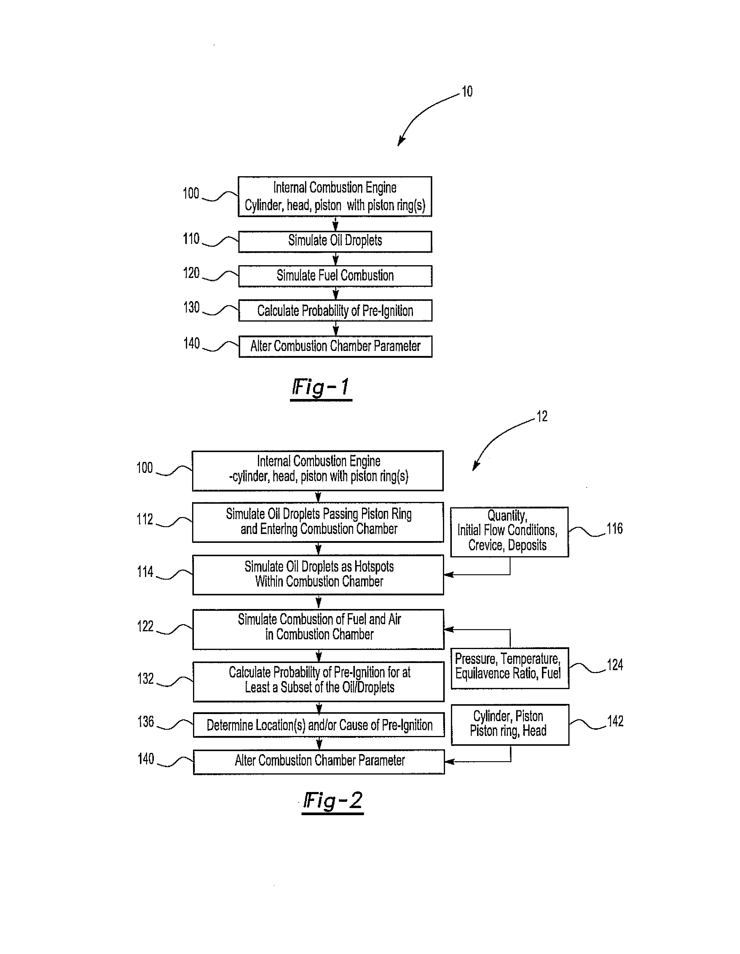
[0022]The present invention provides a process for reducing abnormal combustion within a piston-driven combustion chamber. As such, the present invention has utility for improving engine performance of a motor vehicle.

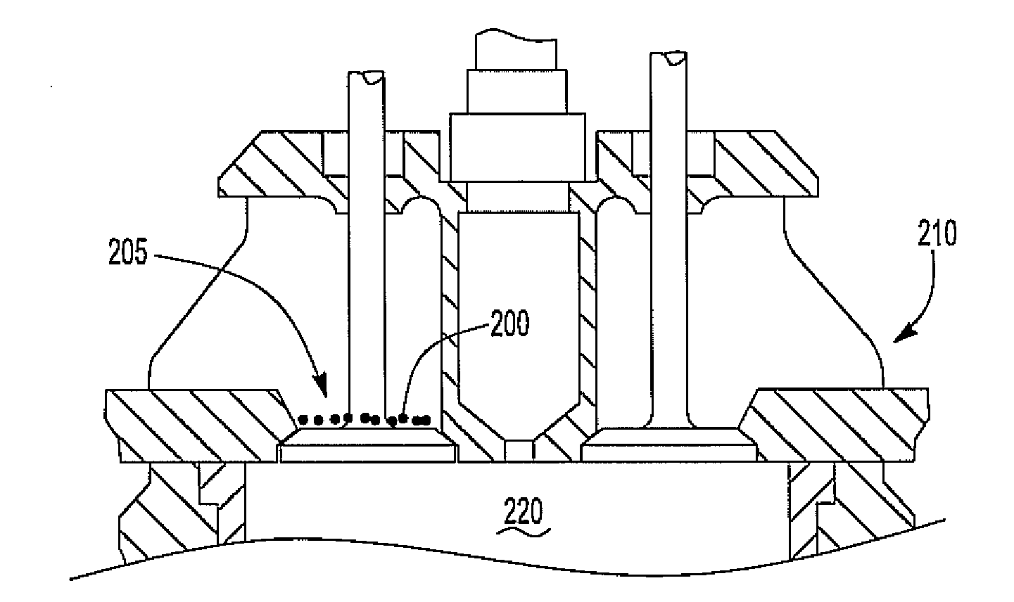
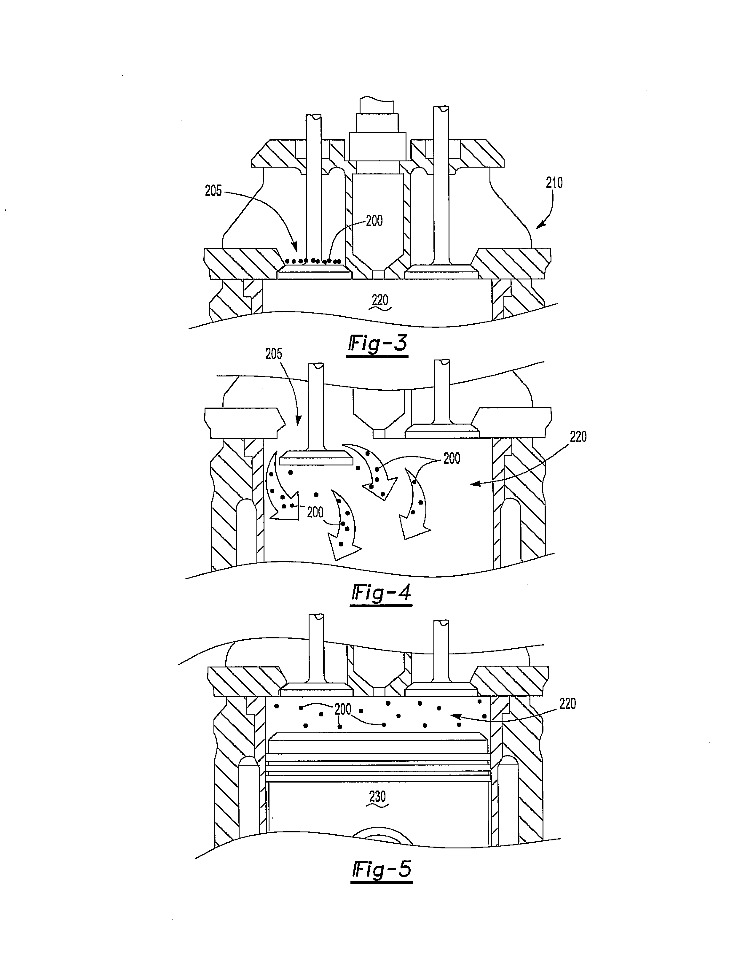
[0023]The process can include providing a piston-driven internal combustion engine. The engine can include a cylinder, a piston with at least one piston ring, a head with an intake and outtake, a crankcase with a crankshaft, the crankcase rotatably connected to the piston as known to those skilled in the art, and with the piston and head forming a combustion chamber as is also known to those skilled in the art. The head can also include one or more valves with valve seats and a spark plug.

[0024]One or more components of the internal combustion engine can be simulated, as can oil passing from the crankcase, past the at least one piston ring and entering into the combustion chamber. In addition, oil droplets entering into the combustion chamber can be simulated as hot sp...


PUM


Abstract

The present invention provides a process for reducing abnormal combustion within a combustion chamber of the engine. The process can include simulation of the piston-driven internal combustion engine with oil droplets from the crankcase entering into the combustion chamber. In addition, the oil drops entering into the combustion chamber can be simulated as hot spots, as can simulation of fuel combustion within the combustion chamber. A probability of pre-ignition for at least a portion of the simulated hot spots as a function of the simulated fuel combustion and the simulated hot spots within the combustion chamber can be calculated and based on the calculation a combustion chamber parameter can be altered such that pre-ignition within the combustion chamber is reduced.

Description

FIELD OF THE INVENTION[0001]The present invention is related to a process for reducing abnormal combustion within a combustion chamber of an internal combustion engine.BACKGROUND OF THE INVENTION[0002]The use of internal combustion engines to generate power is known. In addition, piston-driven internal combustion engines are commonly used in motor vehicles, tractors, lawnmowers, and the like. Such piston-driven internal combustion engines typically have a cylinder, a piston with at least one piston ring, a head, and the like. Fuel is injected into a combustion chamber that is present between the piston, cylinder, and head. The fuel can be mixed with air and combustion of the fuel plus air mixture can provide a rapid expansion within the combustion chamber that drives the piston in a downward or outward direction and results in the rotation of a crankshaft and the production of mechanical power.[0003]Abnormal combustion within the combustion chamber, for example pre-ignition within t...

Claims


Application Information

Patent Timeline
Patent Type & Authority Applications(United States)
IPC IPC(8): F02D41/30
CPCF02F1/00F02D2041/1437F02D35/026F02D35/024F02D35/02F02D41/1404F02D41/1405F02D41/1458F02D41/2454F02D2041/1433
Inventor SHIEH, TENGHUA TOMNITULESCU, OANALIU, WEI LIUYAMASHITA, KIYOTAKA
Owner TOYOTA JIDOSHA KK
Why Eureka
Try Eureka