

System and method for flame stabilization
- Summary
- Abstract
- Description
- Claims
- Application Information
AI Technical Summary
Benefits of technology
Problems solved by technology
Method used
Image

Examples
Embodiment Construction
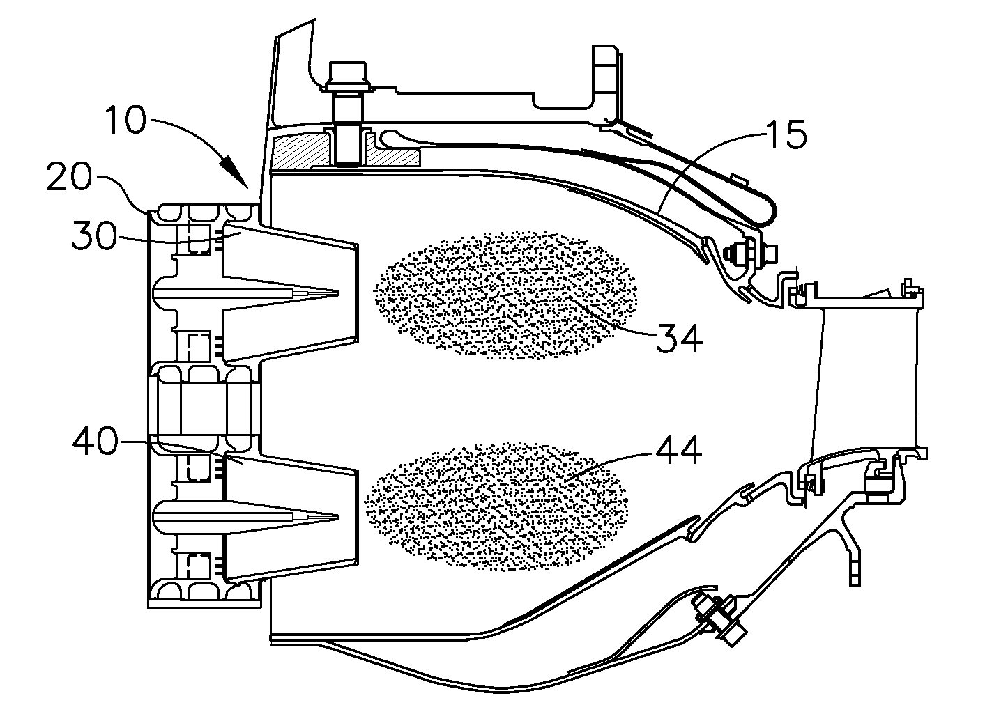
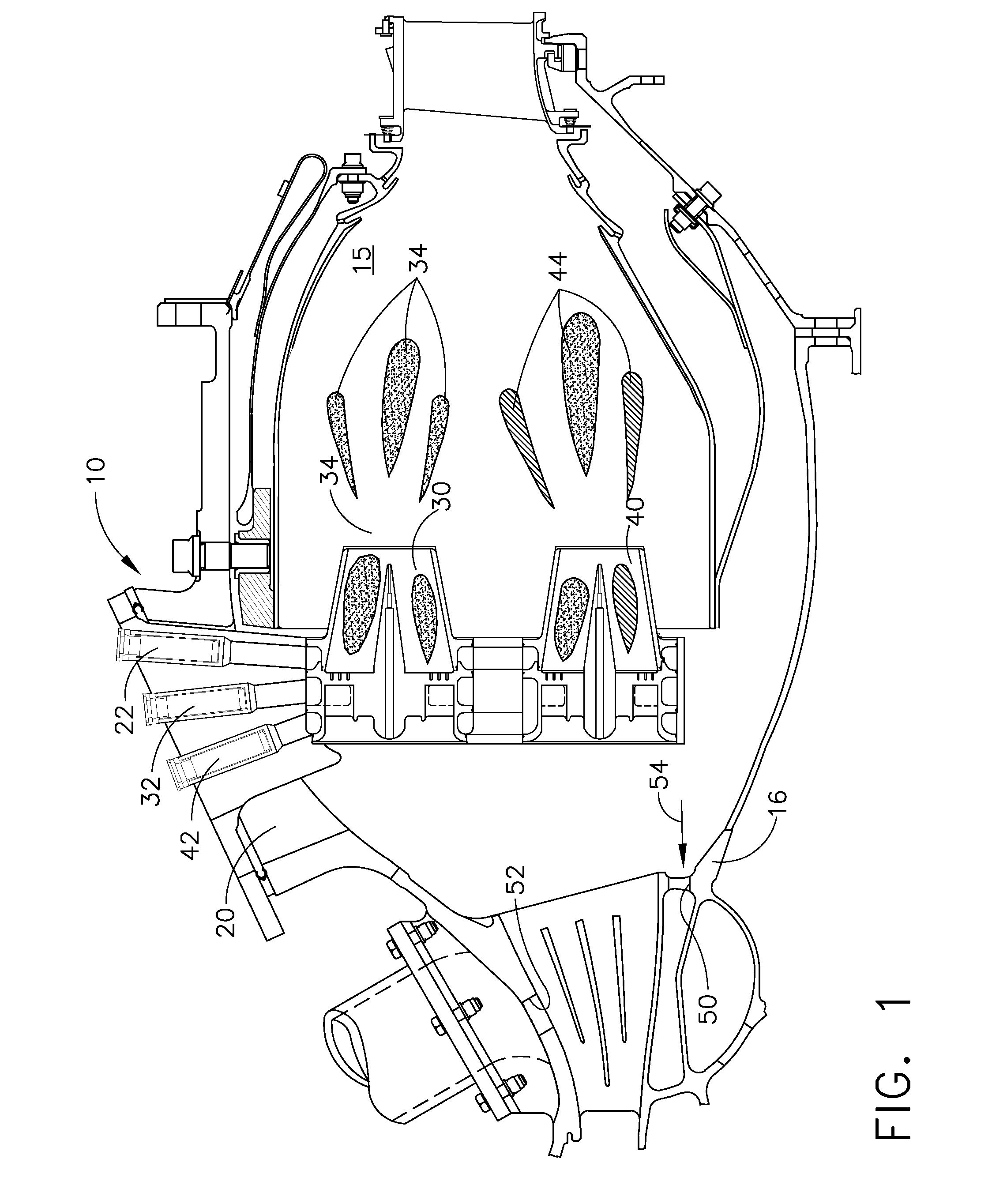
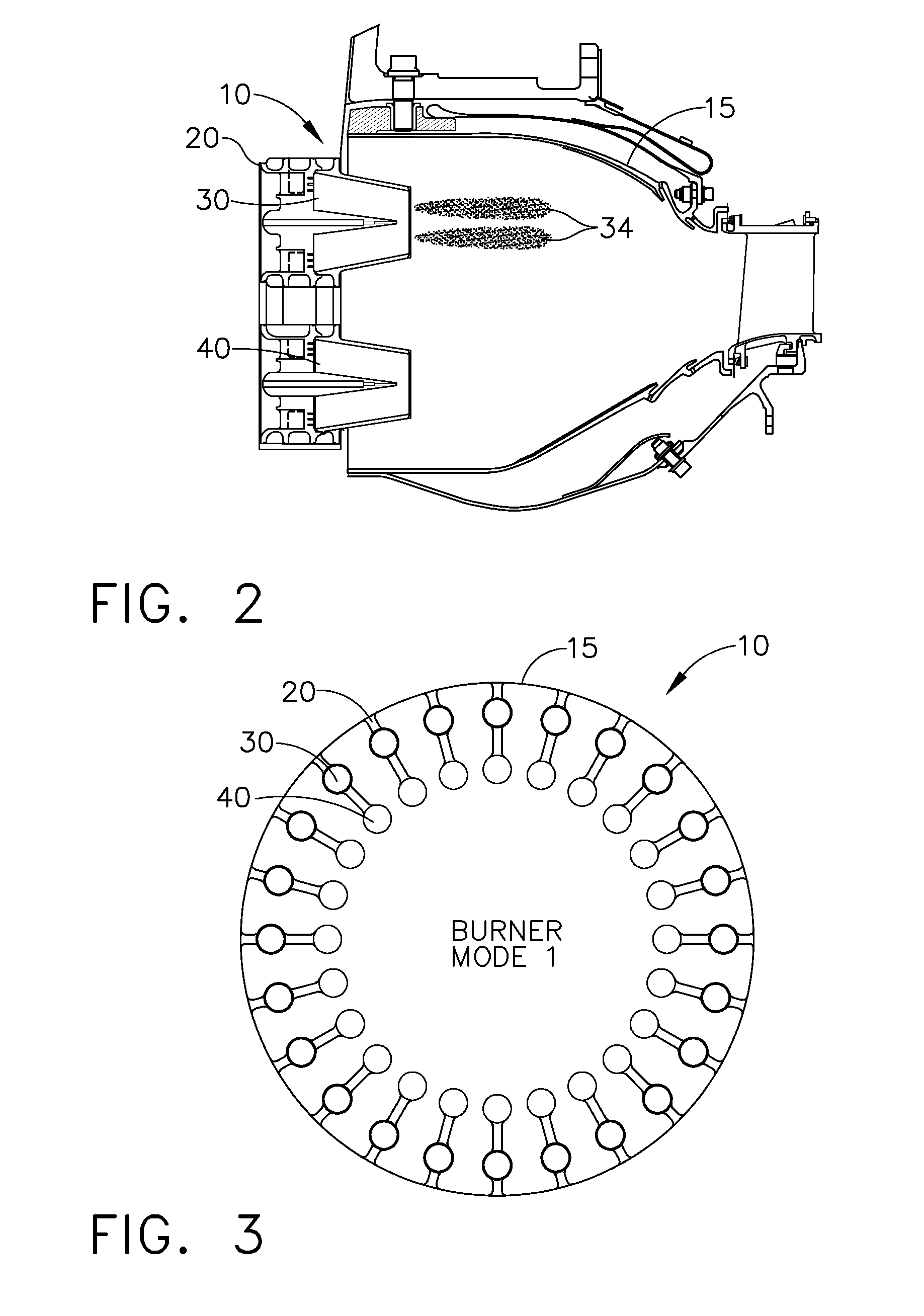
[0026]With reference to FIG. 1, in general, a system for flame stabilization 10 comprises a combustor 15 having one or more premixers 20 with one or more premixed cups. The one or more premixed cups are in fluid communication with one or more Variable ELBO Channels formed therein.
[0027]Embodiments chosen to be illustrated for purposes of example only, not meant to be limiting, include those utilizing two premixed cups wherein the one or more premixed cups include ELBO features and are an A Premixed Cup 30 and a B Premixed Cup 40. Other embodiments not illustrated utilize three or more premixed cups in each premixer. Alternatives include those wherein the one or more premixers number a total of twenty four (24) premixers.
[0028]By way of providing an example of a two-cup premixer embodiment, disposed and formed within each premixer 20 are a Variable ELBO Channel 22, an A Cup Premixed Channel 32 and a B Cup Premixed Channel 42. Variable ELBO Channel 22 serves both the A and B cup, alth...
PUM
 Abstract
Description
Claims
Application Information