
Separator for fuel cell

a fuel cell and separator technology, applied in the direction of cell components, electrochemical generators, cell component details, etc., can solve the problems of inadequate gas supply efficiency and gas supply efficiency of conventional separators used in polymer electrolyte fuel cells, inability to adequately supply fuel gas and oxidizer gas, and inability to adequately balance gas supply efficiency and electricity collection efficiency. , to achieve the effect of increasing the flow of fuel gas or oxidizer gas and facilitating efficient collection of generated electricity

Active Publication Date: 2012-06-26
TOYOTA SHATAI KK
View PDF36 Cites 3 Cited by
  • Summary
  • Abstract
  • Description
  • Claims
  • Application Information

AI Technical Summary

Benefits of technology

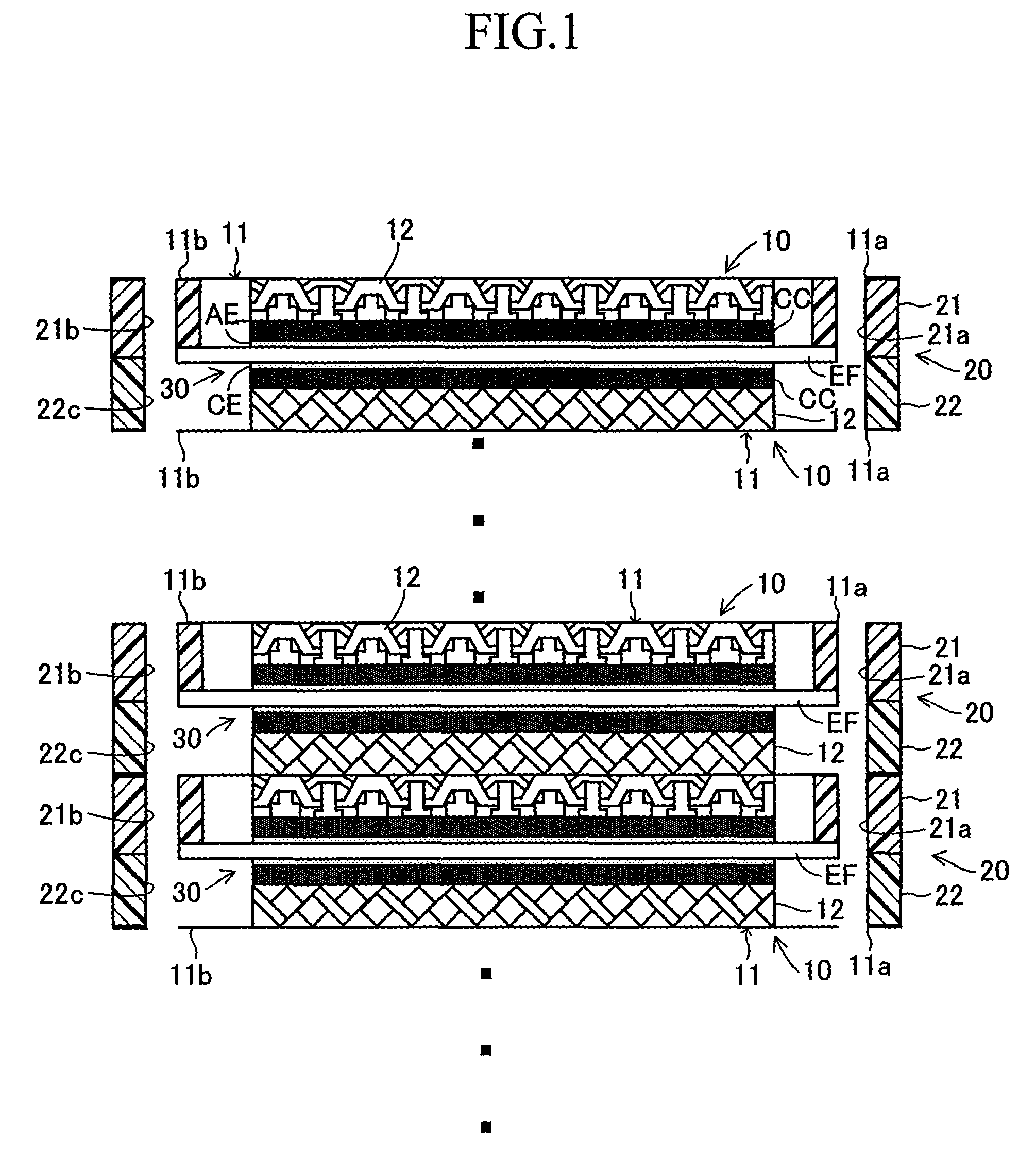
The present invention provides a separator for a fuel cell that allows good supply of gas and efficient collection of generated electricity to improve electricity generation efficiency of the fuel cell. The separator comprises a flat-sheet-like separator body and a collector formed from a metal lath with a large number of through holes, each with a predetermined opening shape. The collector forms a gas passageway between the separator body and the electrode layers for supplying fuel gas or oxidizer gas to the electrode layers and collecting electricity generated through electrode reactions in the electrode layers. The contact area between the collector and the electrode layer is equal to or greater than the contact area between the collector and the separator body, ensuring sufficient supply of gas required for electrode reactions and efficient collection of generated electricity. The metal laths can differ in the ratio of total opening area of through holes to a surface area to optimize the contact area and gas supply. The invention allows for increased gas supply efficiency and efficient collection of generated electricity.

Problems solved by technology

Thus, limitations are imposed on a contact area between supplied fuel gas and the anode electrode layer and that between supplied oxidizer gas and the cathode electrode layer, possibly resulting in a failure to sufficiently supply fuel gas and oxidizer gas.
As mentioned above, a separator which has conventionally been employed in the polymer electrolyte fuel cell is inferior in terms of efficient supply of gas, but is superior in terms of efficient collection of electricity.
In other words, gas supply efficiency and electricity collection efficiency are not appropriately balanced.
In other words, the area of surface portions of the anode electrode layer or the cathode electrode layer covered with the second member increases, possibly resulting in a failure to supply gas to the anode electrode layer or the cathode electrode layer in an amount required for an electrode reaction.
However, generally, the cost of manufacturing porous metal is very high; thus, the cost of manufacturing a fuel cell which employs porous metal increases.

Method used


Image

  • Separator for fuel cell
  • Separator for fuel cell
  • Separator for fuel cell

Examples


first modified embodiment

[0070]As shown in FIG. 7A, through holes formed in the metal lath can each have, for example, a diamond shape (quadrangular shape). Next will be described a first modified embodiment which employs a metal lath having through holes each having a diamond shape. A metal lath RM′ having through holes each having a diamond shape (hereinafter, these through holes are called diamond through holes) is formed also by use of, for example, the lath machining apparatus A used in the above-described embodiment. However, in formation of the metal lath RM′, the upper blade UH of the blade stamp H differs in cutting-edge shape from the above-described embodiment.

[0071]Specifically, in the first modified embodiment, the cutting edge of the upper blade UH has a plurality of angular crests and angular bottoms (generally triangular shapes) corresponding to a diamond shape which is imparted to through holes to be formed. Also, in the first modified embodiment, the lath machining apparatus A operates as ...

second modified embodiment

[0079]In the above-described first modified embodiment, the collector 12′ is formed from the metal lath RM′ in which diamond through holes are formed in a meshy, step-like arrangement. In place of the metal lath RM′, a metal lath RM″ in which through holes each have a generally pentagonal shape can be employed. Next will be described a second modified embodiment which employs the metal lath RM″.

[0080]As shown in FIG. 9A, the metal lath RM″ of the second modified embodiment has through holes which each have a generally pentagonal shape and which are formed in a meshy, step-like arrangement (hereinafter, the through holes each having a pentagonal shape are called pentagonal through holes). This metal lath RM″ is formed also by use of, for example, the lath machining apparatus A. However, in formation of the metal lath RM″, the upper blade UH of the blade stamp H differs in cutting-edge shape from the above-described embodiment and first modified embodiment.

[0081]In the second modified...


PUM

PropertyMeasurementUnit
thicknessaaaaaaaaaa
electrically conductiveaaaaaaaaaa
areaaaaaaaaaaa

Abstract

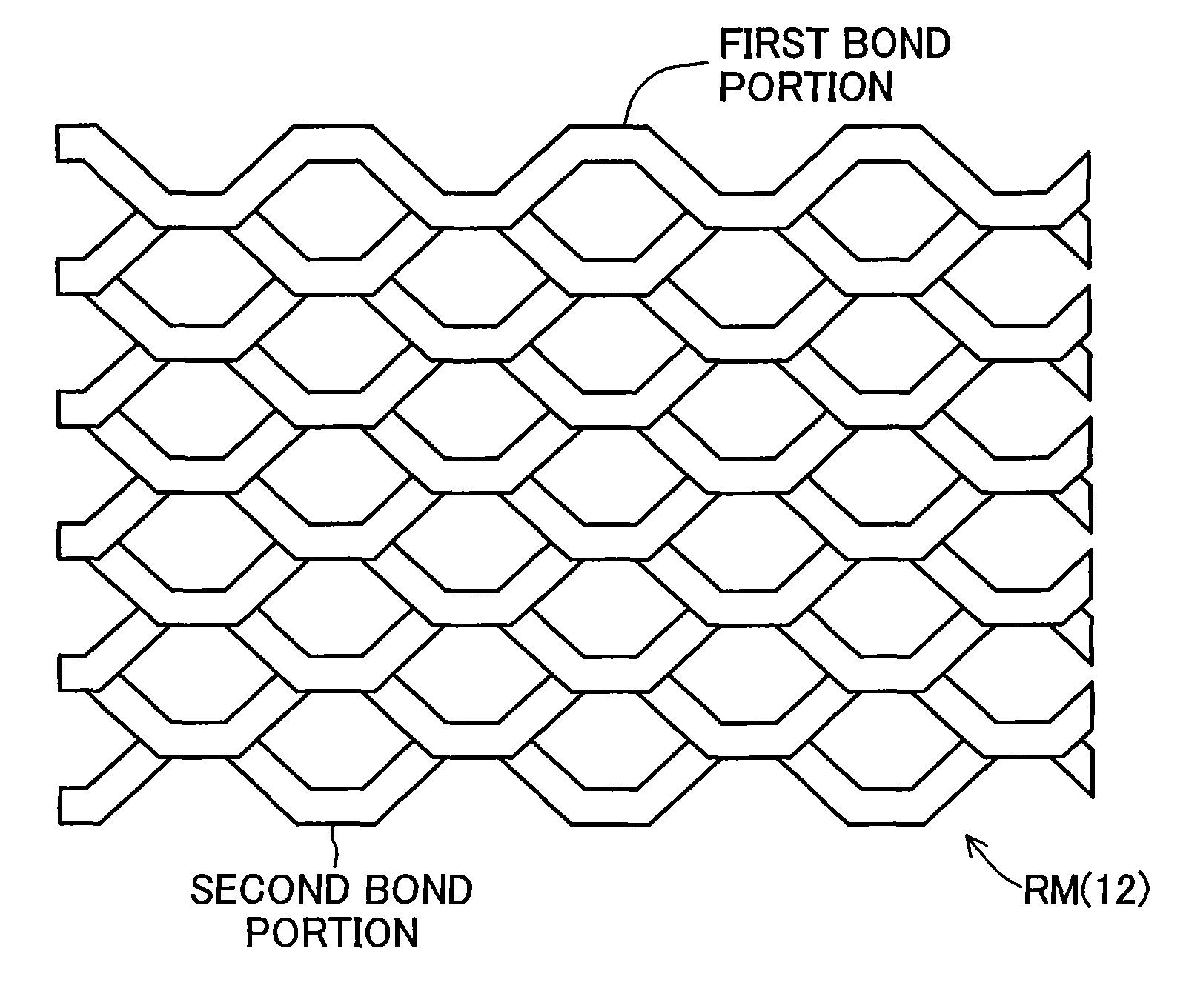
A separator includes a separator body 11 and a collector 12. The separator body 11 prevents a mixed flow of fuel gas and oxidizer gas. The collector 12 is formed from a metal lath RM in which through holes each having an opening shape assuming the form of a hexagon are formed in a meshy, step-like arrangement. This establishes a substantially linear contact mode between the collector 12 and each of the separator body 11 and a carbon cloth CC superposed on an MEA 30. This contact mode increases a contact area between the carbon cloth CC and gas and allows a necessary and sufficient contact area between the carbon cloth CC and the separator body 11. Thus, gas can be supplied efficiently, and generated electricity can be collected efficiently to thereby improve electricity generation efficiency of a fuel cell.

Description

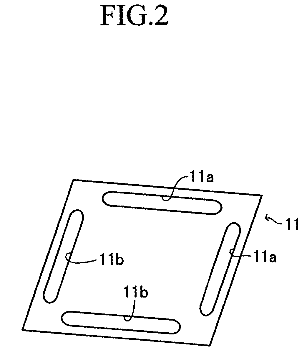
TECHNICAL FIELD[0001]The present invention relates to a separator for use in a fuel cell, particularly, a polymer electrolyte fuel cell.BACKGROUND ART[0002]Generally, a polymer electrolyte fuel cell includes a membrane-electrode assembly which, in turn, includes an anode electrode layer formed on one side thereof and a cathode electrode layer formed on the other side thereof. Fuel gas (e.g., hydrogen gas) and oxidizer gas (e.g., air) are supplied to the anode electrode layer and the cathode electrode layer, respectively, via respective separators. Supply of fuel gas and oxidizer gas to the anode electrode layer and the cathode electrode layer induces electrode reactions in the membrane-electrode assembly, thereby generating electricity. Electricity generated in the membrane-electrode assembly is output to the exterior of the fuel cell via the separators.[0003]The polymer electrolyte fuel cell generates electricity efficiently by means of efficiently supplying fuel gas and oxidizer g...

Claims


Application Information

Patent Timeline
Patent Type & Authority Patents(United States)
IPC IPC(8): H01M8/04
CPCH01M8/0232H01M8/0247H01M8/0297H01M8/0202H01M8/242H01M2008/1095Y02E60/50H01M8/026H01M8/0258
Inventor HASHIMOTO, KEIJI
Owner TOYOTA SHATAI KK
Learn More