Check patentability & draft patents in minutes with Patsnap Eureka AI!

Sensor for belt retractor

a technology of sensor and retractor, which is applied in the direction of belt retractor, instrument, measurement device, etc., can solve the problems of repetitive locking and unlocking of the primary restraint, inconvenient use design, and inability to meet the needs of all vehicles, so as to reduce potential nuisance locks

Active Publication Date: 2006-03-21
AUTOLIV ASP INC +6
View PDF40 Cites 7 Cited by
  • Summary
  • Abstract
  • Description
  • Claims
  • Application Information

AI Technical Summary

Benefits of technology

The solution enhances comfort and compliance with FMVSS regulations by reducing nuisance locks while maintaining sensitivity to essential accelerations, allowing the sensor to be adaptable across various vehicle types and applications.

Problems solved by technology

A common use design may not be suitable for all vehicles since some vehicles are stiffer or more dynamic than others depending on the road conditions.
Generally, as the vehicle becomes more subject to road induced accelerations, so does the sensor, creating occupant restraint comfort issues.
Such vehicles and common use sensors typically generate hypersensitive retractors, resulting in a repetitive locking and unlocking of the primary restraint, an event commonly referred to as a retractor nuisance lock.
Nuisance locks often cause the primary restraint / belts to bite / cinch down on the occupant, restricting occupant movement and causing discomfort to the occupant.
Locking of the retractor in response to non-impact or non-rollover events is undesirable as it is an annoyance to the occupants.
However, most nuisance locking conditions are generated by a sensor's inability to eliminate or reduce the influence of undesired sensitivity along the “Z” (or vertical) direction.
For example, bumps in the road cause the sensor mass to bounce in the “Z” direction, potentially causing the retractor to lock / limit belt displacement.
Most often these potential locking conditions result in the retractor to lock, resulting in a nuisance lock and discomfort to the occupant being restrained.
Unfortunately, when these critical characteristics are modified, the sensor is likely to become unique to a restraint / retractor, an application, an installation or a specific vehicle.
The common use sensor, therefore, becomes less suited for diverse applications and is not well suited for the high volume, low cost demands of the automotive industry.
Changes such as those mentioned also have the potential of making the sensor become less sensitive and even non-compliant with ECE or FMVSS regulatory performance requirements.

Method used


Image

  • Sensor for belt retractor
  • Sensor for belt retractor
  • Sensor for belt retractor

Examples


Embodiment Construction

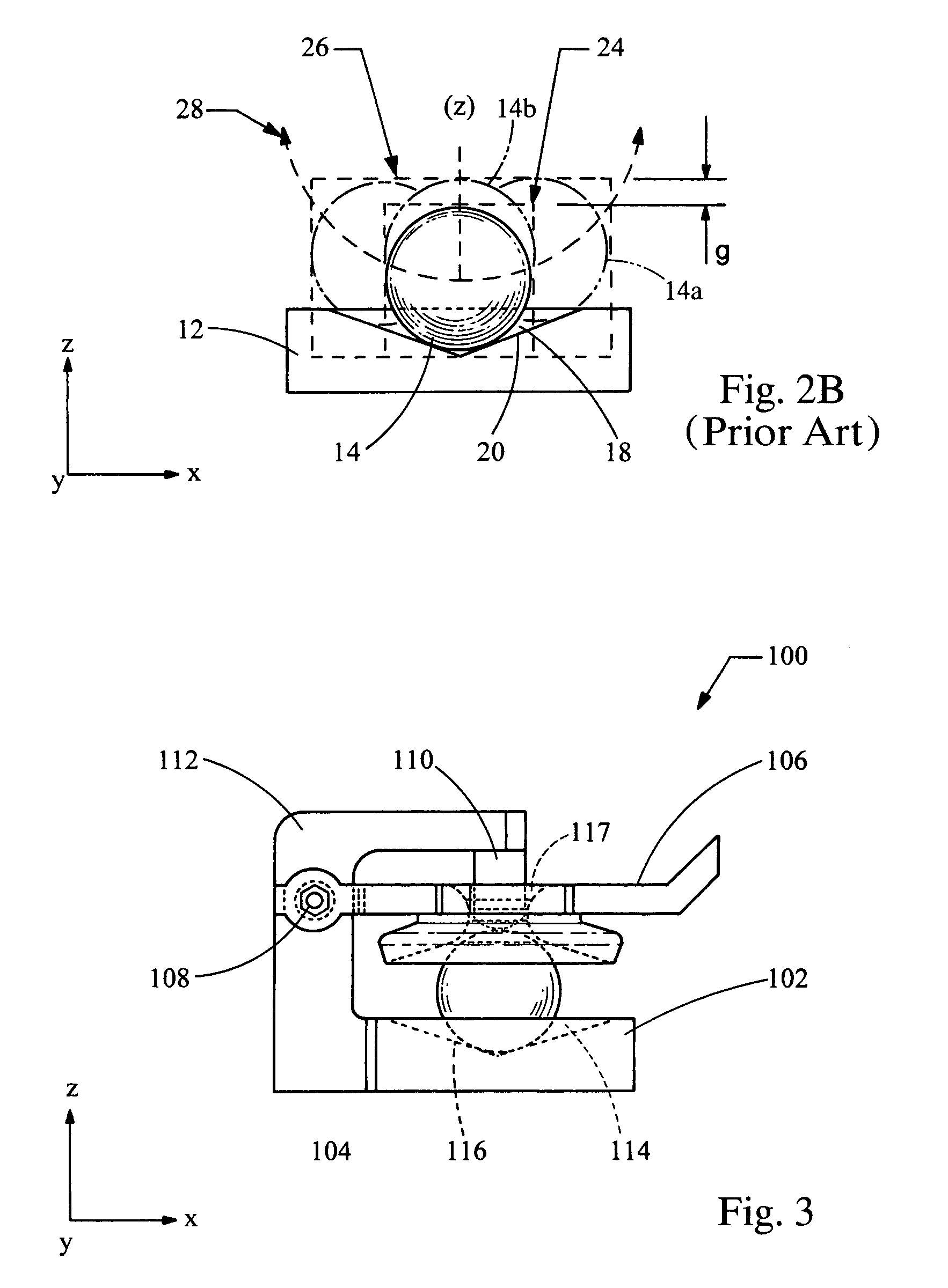
[0018]Referring to FIG. 1, there is shown a conventional primary restraint sensor 10 including a sensor housing 12, a mass 14, and a lever arm 16. The bottom portion of the housing 12 defines an indentation 18 with an inclined plane 20. When undisturbed, the mass 14, shaped as a sphere, rests at the bottom of the indentation 18, and the lever arm 16 attached to the upper portion of the housing 12 at a pivot point 21 rests on top of the mass 14, unengaged with a ratchet 22. A Cartesian coordinate system XYZ is shown in FIG. 1, as well as in the subsequent figures, for convenience, where the Z axis is typically aligned with gravitational forces. Vertical movement between the mass 14 and housing 12 is defined as movement along the Z direction and lateral movements are defined as movements in along the X and Y directions.

[0019]As a vehicle in which the restraint sensor 10 is mounted maneuvers over a road, the mass 14 moves up the incline plane 20 as designated at 14a and / or bounces up a...


PUM

PropertyMeasurementUnit
inertial forcesaaaaaaaaaa
massaaaaaaaaaa
displacementaaaaaaaaaa

Abstract

A sensor for a vehicle belt retractor includes a housing, an excitation mass, a locking mechanism which locks the belt retractor, and a lever arm connected to the housing. The lever arm is in contact with the excitation mass and engages the locking mechanism when the excitation mass moves relative to the housing. The sensor further includes a damper that restricts vertical displacement of the excitation mass relative to the housing.

Description

BACKGROUND[0001]This invention relates to a sensor for a vehicle seat belt retractor. More specifically, the present invention relates to a sensor that reduces or eliminates nuisance locks of seat belt retractors.[0002]In order to provide enhanced comfort and convenience, seat belt retractors employ a mechanism to allow the belt webbing to be freely extended and retracted from the retractor as the vehicle occupant moves in the seat. Of course, in order to provide its occupant protection function, the retractor must lock to prevent webbing pullout as the occupant loads the belt in an impact condition. Most vehicles incorporating such so called emergency locking retractors employ a pendulum or roll ball type inertia sensor in the retractor.[0003]Sensor strategies employed in primary occupant restraint applications must be capable of sensing low “g” or vehicle tilt angles generated during sudden vehicle braking conditions or vehicle roll over events. Sensing these vehicle conditions re...

Claims


Application Information

Patent Timeline
Patent Type & Authority Patents(United States)
IPC IPC(8): G01N3/08B60R22/38B60R22/40
CPCB60R22/40
Inventor KNOX, MATTHEW J.
Owner AUTOLIV ASP INC
Features
  • R&D
  • Intellectual Property
  • Life Sciences
  • Materials
  • Tech Scout
  • Unparalleled Data Quality
  • Higher Quality Content
  • 60% Fewer Hallucinations
Learn More