AI technical title is built by Patsnap AI team. It summarizes the technical point description of the patent document.
a technology of product display rack and front barrier, which is applied in the direction of identification means, show hangers, instruments, etc., can solve the problems of subject matter and somewhat higher molding costs, and achieve the effect of high level of clarity and transparency
Active Publication Date: 2006-04-25
TRION IND
View PDF10 Cites 73 Cited by
Summary
Abstract
Description
Claims
Application Information
AI Technical Summary
This helps you quickly interpret patents by identifying the three key elements:
Problems solved by technology
Method used
Benefits of technology
Benefits of technology
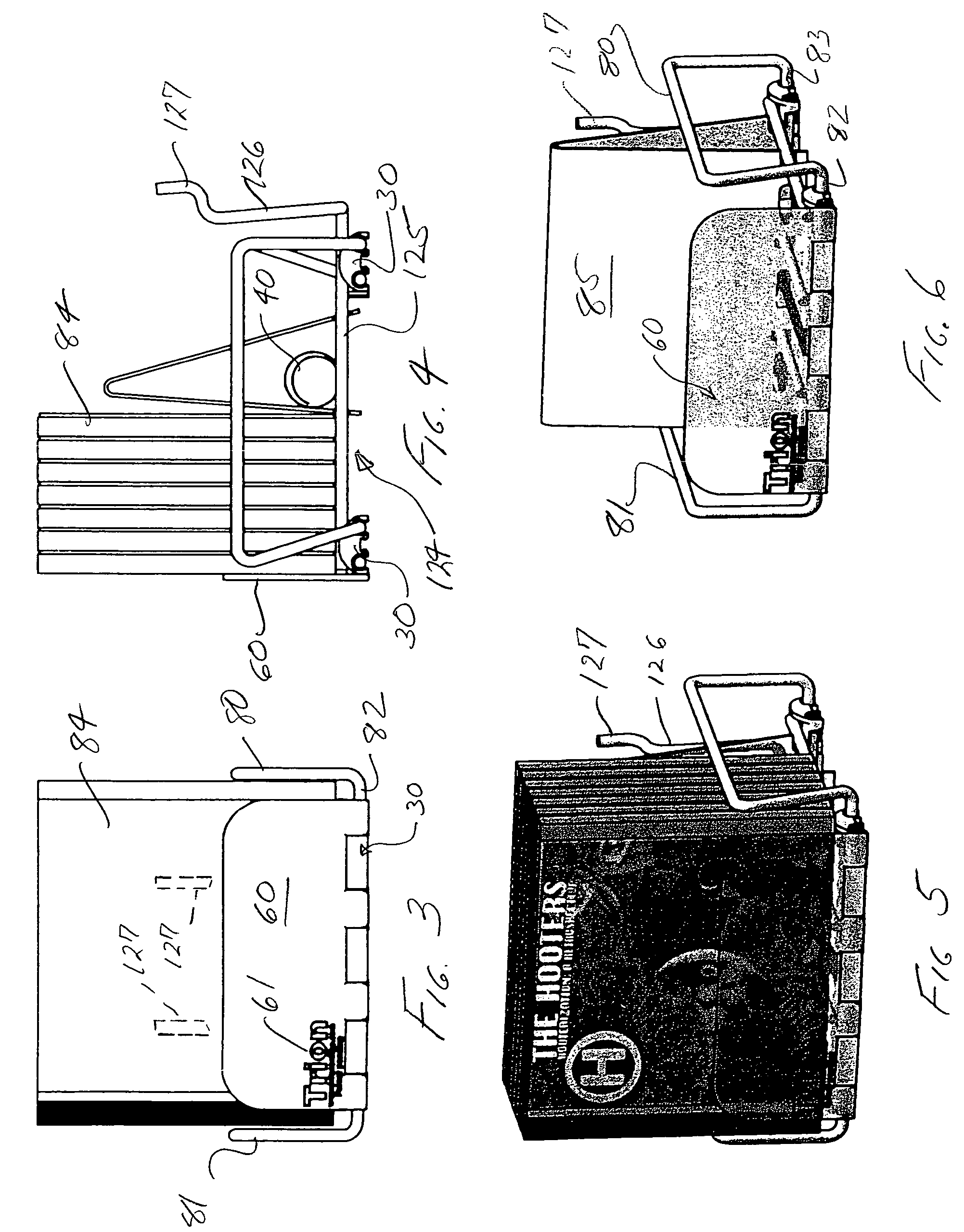
[0005]The present invention provides a product display device of the general type described above, comprising a wire product support structure mounted at its opposite ends by plastic base elements and provided with a pusher sled for urging displayed product items to the front of the display. At the front of the display device, a barrier panel is provided to limit forward movement of the displayed product items. The barrier panel preferably is formed of a clear, transparent, strong plastic material, such as polycarbonate, and is formed by injection molding, rather than by extrusion, for example, in order to achieve a high level of clarity and transparency.
Problems solved by technology
Conceptually, of course, the barrier panels could be provided in a variety of widths as well as various heights, subject of course to somewhat higher molding costs as a function of the greater number of molds required to achieve various barrier panel sizes.
Method used
Image
Click on the blue label to locate the original text in one second.
Reading with bidirectional positioning of images and text.
Examples
Embodiment Construction
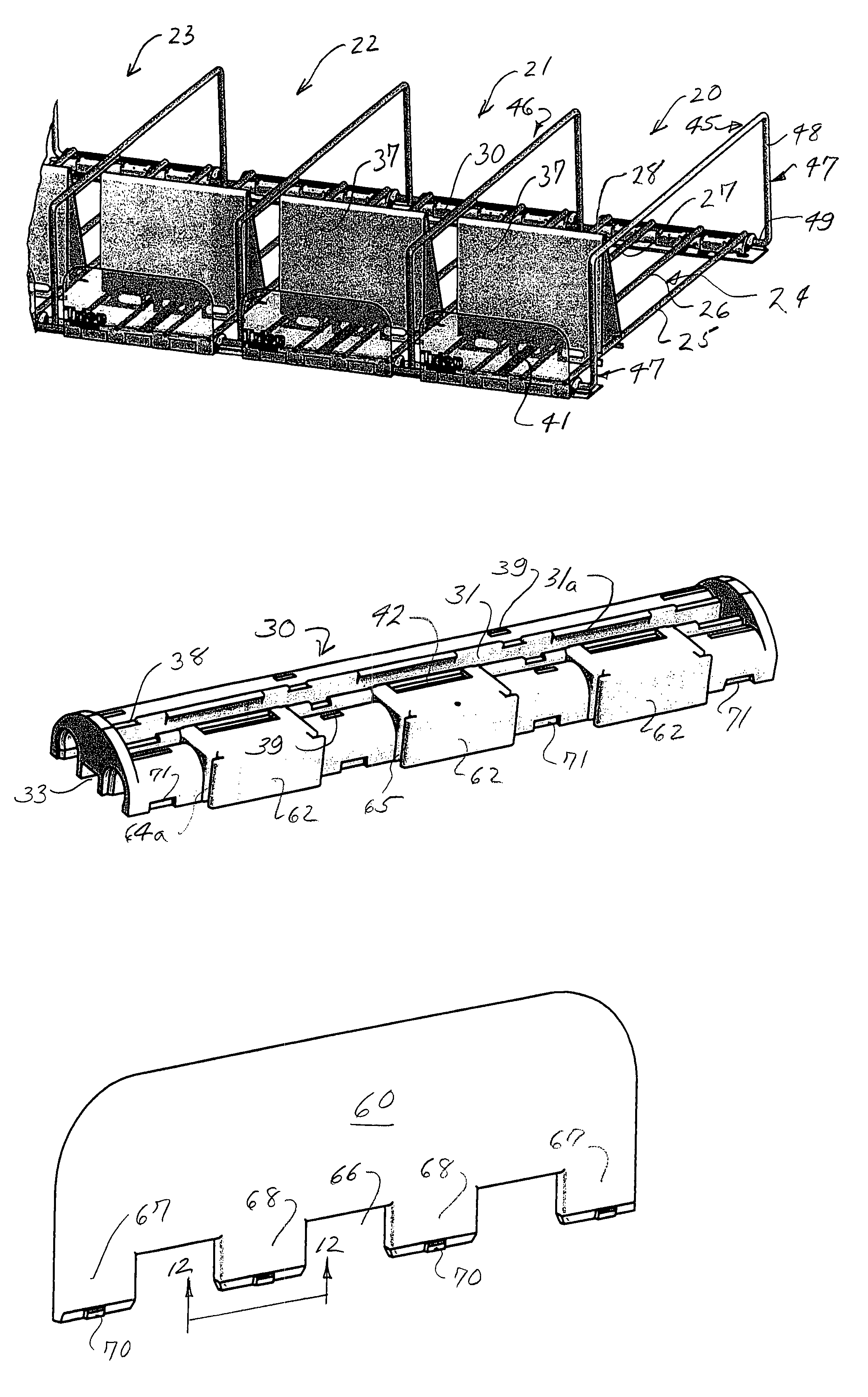
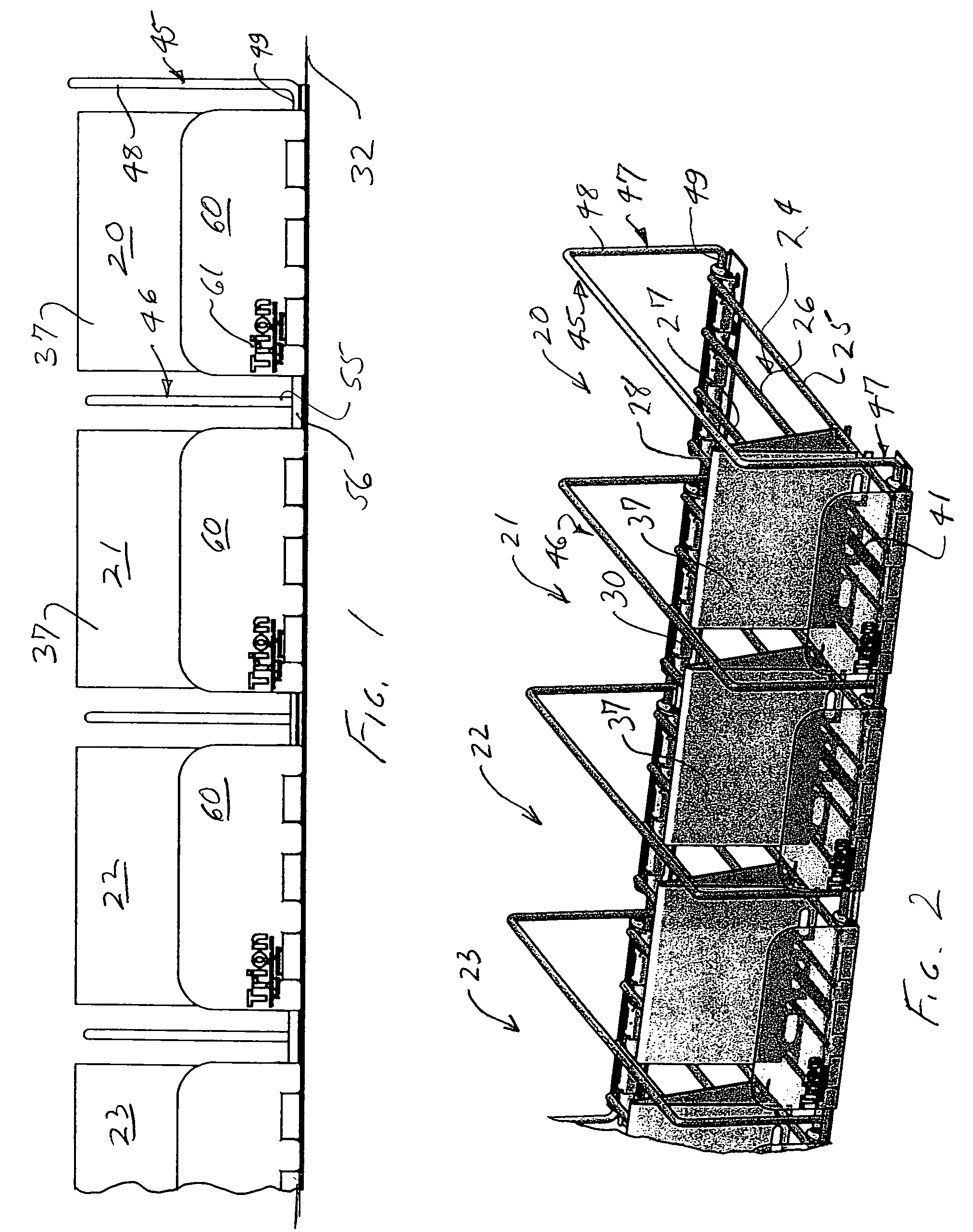
[0018]Referring now to the drawings and initially to FIGS. 1–2 thereof, there is shown a multi-unit product display incorporating a plurality of display devices according to the invention. In FIGS. 1 and 2, three complete units are shown and a portion of a fourth unit. Each of the units, designated generally by the reference numerals 20–23. Each display unit comprises a product support designated generally by the numeral 24 and comprising four longitudinally extending, straight wire support elements 25–28, extending from front to back in spaced-apart, parallel relation and defining a support plane for products to be displayed (not shown). Adjacent their front and back end extremities, the wire support elements are joined underneath by cross bar wires 29 (FIG. 13), typically welded thereto, to form a structurally rigid platform.
[0019]At each end, the wire product supports 24 are mounted on front and back plastic base elements 30, shown in detail in FIGS. 7–10 and 13, and to be descri...
PUM
Abstract
A product display device is comprised of a wire base structure with a plurality of spaced-apart, straight parallel wire supports extending in a front-to-back direction, and wire cross bars underlying the wire supports adjacent their front and back ends. Plastic base elements are snap-fitted to the cross bars at the front and back ends of the wire base structure, and a pusher is provided on the base structure for urging displayed product items toward the front. A molded plastic barrier panel is mounted at the front of the front base element by vertical tabs which are received in vertical grooves at the front of the base element. The plastic barrier panel can be made of clear, transparent material for optimum viewing of the product being displayed. The panels can accommodate the presence of product identifying logos, graphics or other special information associated with a particular product.
Description
RELATED APPLICATIONS[0001]This application is related to the Thomas O. Nagel, et al. U.S. applications Ser. No. 10 / 024,153, filed Dec. 17, 2001, now U.S. Pat. No. 6,719,152, granted Apr. 13, 2004, and Ser. No. 10 / 406,984, filed Apr. 4, 2003, now U.S. Pat. No. 6,866,156, granted Mar. 15, 2005, as well as to the Thomas O. Nagel U.S. applications Ser. No. 10 / 219,800, filed Aug. 16, 2002, now U.S. Pat. No. 6,745,906, granted Jun. 8, 2004, and Ser. No. 10 / 323,461, filed Dec. 18, 2002, now U.S. Pat. No. 6,866,155, granted Mar. 15, 2005. All of the foregoing are assigned to the assignee of this application, Trion Industries, Inc., Wilkes-Barre, Pa.BACKGROUND OF THE INVENTION[0002]The invention relates to product display systems, particularly but not exclusively to wire-based product display devices provided with width-adjustable side guides and spring-actuated pusher mechanisms for maintaining displayed product items at the front of the display device. The Nagel and Nagel et al. applicatio...
Claims
Application Information
Patent Timeline
Application Date:The date an application was filed.
Publication Date:The date a patent or application was officially published.
First Publication Date:The earliest publication date of a patent with the same application number.
Issue Date:Publication date of the patent grant document.
PCT Entry Date:The Entry date of PCT National Phase.
Estimated Expiry Date:The statutory expiry date of a patent right according to the Patent Law, and it is the longest term of protection that the patent right can achieve without the termination of the patent right due to other reasons(Term extension factor has been taken into account ).
Invalid Date:Actual expiry date is based on effective date or publication date of legal transaction data of invalid patent.

