Unlock instant, AI-driven research and patent intelligence for your innovation.

Crankcase emission control device

Active Publication Date: 2006-05-23
AICHI MASCH IND CO LTD
View PDF12 Cites 25 Cited by
  • Summary
  • Abstract
  • Description
  • Claims
  • Application Information

AI Technical Summary

Benefits of technology

[0005]However, in some of the known crankcase emission control devices including the above-mentioned disclosed device, the gas / liquid separator has been designed without giving a careful consideration to the size of the same, particularly the height of the same. When the height of the separator increases, the height of the cylinder head cover increases and thus in this case, the height of the entire construction of the engine increases, which restricts the freedom to design the engine room hood as well as the freedom to layout the various parts in the engine room.

Problems solved by technology

However, in some of the known crankcase emission control devices including the above-mentioned disclosed device, the gas / liquid separator has been designed without giving a careful consideration to the size of the same, particularly the height of the same.
When the height of the separator increases, the height of the cylinder head cover increases and thus in this case, the height of the entire construction of the engine increases, which restricts the freedom to design the engine room hood as well as the freedom to layout the various parts in the engine room.

Method used


Image

  • Crankcase emission control device
  • Crankcase emission control device
  • Crankcase emission control device

Examples


Embodiment Construction

[0014]In the following, the present invention will be clearly described with reference to the accompanying drawings.

[0015]For ease of understanding, various directional terms, such as, right, left, upper, lower, rightward and the like are used in the following description. However, such terms are to be understood with respect to only a drawing or drawings on which a corresponding part or portion is shown.

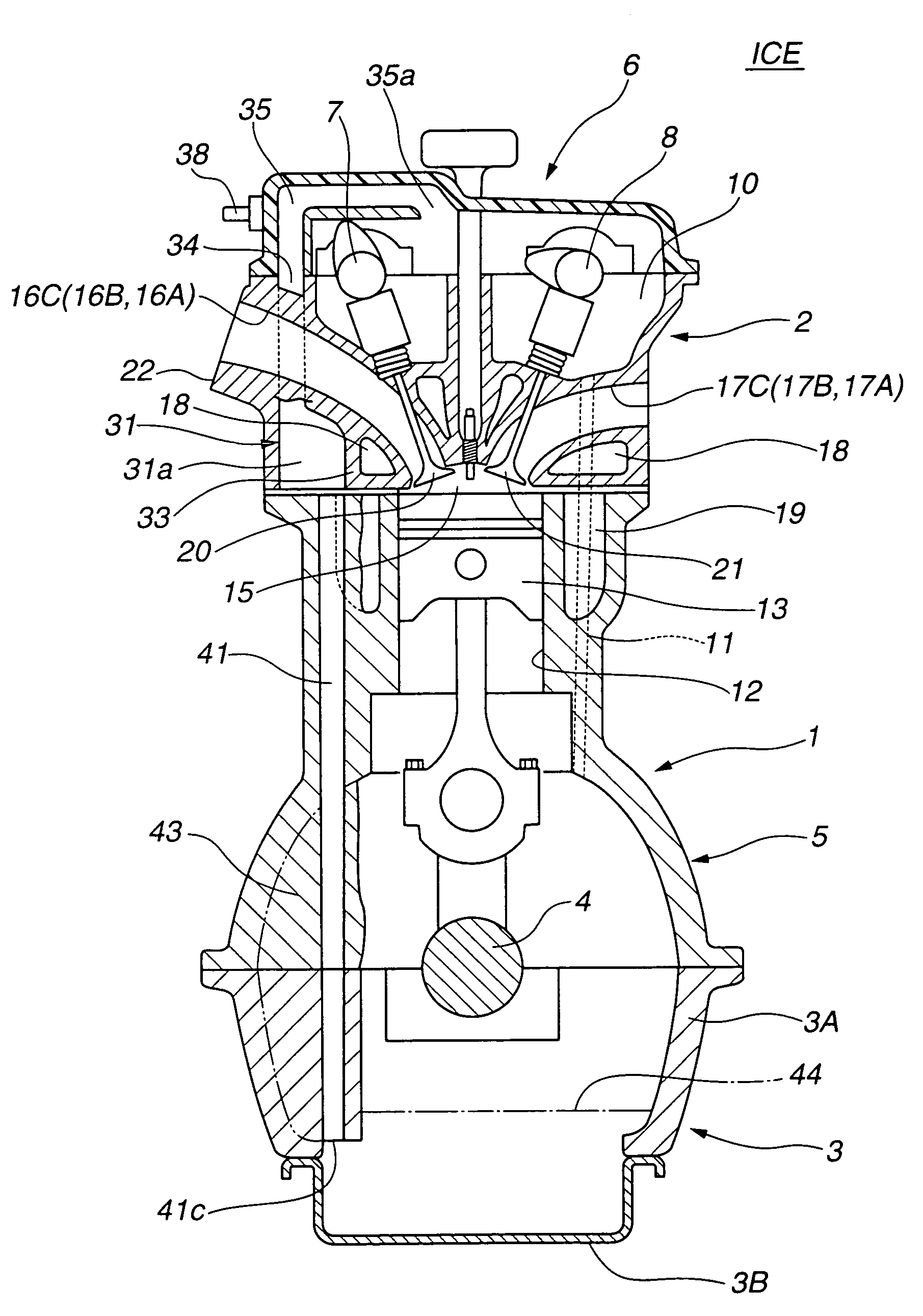
[0016]Referring to the drawings, particularly, FIGS. 1 and 2, there is shown an internal combustion engine ICE that is provided with a crankcase emission control device of the present invention.

[0017]The engine ICE shown is of a three-cylinder in-line type that generally comprises a cylinder block 1, a cylinder head 2 mounted on cylinder block 1, and an oil pan 3 mounted beneath cylinder block 1.

[0018]In the illustrated engine ICE, oil pan 3 comprises an upper pan part 3A that is cast from aluminum alloy and a lower pan part 3B that is produced by stamping a steel plate. As shown, l...


PUM


Abstract

A crankcase emission control device of an internal combustion engine comprises a gas / liquid separator that separates an oil mist from blow-by gases flowing therethrough. A first passage is defined in both a crankcase and a cylinder head to connect an interior of the crankcase to a valve rocker cover chamber defined by the cylinder head. A second passage extends from the valve rocker cover chamber to the gas / liquid separator. A third passage extends from the gas / liquid separator to an intake system of the engine. For reducing the height of the entire construction of the engine, the gas / liquid separator is integrally formed by the cylinder head at a position below intake ports of the cylinder head.

Description

BACKGROUND OF THE INVENTION[0001]1. Field of the Invention[0002]The present invention relates in general to an emission control device of an internal combustion engine, and more particularly to a crankcase emission control device that positively routes blow-by gases from the crankcase to the intake system of the engine. More specifically, the present invention relates to the crankcase emission control devices of a type that positively routes blow-by gases from the crankcase to the intake system through a valve rocker cover chamber of the cylinder head and a gas / liquid separator defined by the cylinder head.[0003]2. Description of the Related Art[0004]Hitherto, various crankcase emission control devices have been proposed and put into practical use in the field of internal combustion engines that are mounted in wheeled motor vehicles. Almost all them are of a type wherein by introducing fresh air into the crankcase, blow-by gases in the crankcase are enforcedly led to the intake syst...

Claims


Application Information

Patent Timeline
IPC IPC(8): F01M13/00F01M13/04F01M13/02F02F1/24F02F7/00
CPCF01M13/022
Inventor OOKAWA, HISAOMASUBUCHI, MICHIHIROHADA, MASATOSHI
Owner AICHI MASCH IND CO LTD