Electric plant and method and use in connection with such plant

a technology of electric plants and circuits, applied in the field of electric plants, can solve the problems of high current and a voltage drop in large parts of the network, mechanical and thermal strain on all apparatus and equipment, and incur the risk of personal injury, so as to reduce short-circuiting currents, increase competitive strength, and increase reliability

Inactive Publication Date: 2006-07-18
ABB TECH AG
View PDF10 Cites 40 Cited by
  • Summary
  • Abstract
  • Description
  • Claims
  • Application Information

AI Technical Summary

Benefits of technology

[0031]For optimal safety a closing contact should be arranged in connection with each feeder cable to the switchgear installation. Such an embodiment is extremely important in order to eliminate arcs in the switchgear installation itself, and provides increased reliability for reducing short-circuiting currents in the event of faults out in the consumer system. This thus constitutes another preferred embodiment of the invention.
[0032]As mentioned earlier, it is desirable to effect closing as quickly as possible. This offers increased competitive strength over alternative safety measures achieved by breaking. Thanks to short closing time the solution is particularly attractive even for remedying faults out in the consumer system where a breaker is not as slow as in the feeder cable. It is also important in this case for the closing to occur during the first periodic quarter. A closing contact has recently been developed that can close to earth in less than 5 ms in the medium voltage area. The use of a quick-action closing contact therefore constitutes yet another preferred embodiment of the claimed switchgear installation.

Problems solved by technology

The consequences of a short circuit are a high current and a voltage drop in large parts of the network.
The short-circuiting current also causes mechanical and thermal strain on all apparatus and equipment upstream of the fault location.
In most cases an arc occurs in the fault location which, in combination with the high short-circuiting current, produces damages at the fault location that demand repairs but also incur risk of personal injury.
Extremely large quantities of energy in the form of heat and radiation are released in arcs caused by large leakages.
This energy gives rise to pressure increases in enclosed switchgear installations with restricted space, for instance, which may burst the enclosure.
The high arc temperatures also cause the material in conductors and coupling equipment to melt, or even to be vaporised.
The arc also gives rise to toxic gases through decomposition of air (NOx) and vaporisation of metals.
Such switchgear installations therefore become space consuming and expensive.
Besides being expensive, these breakers have the drawback of reacting relatively slowly.
A breaking time of 200 ms is too long to effectively prevent damage as a result of arcs being formed.
For practical reasons, this method is not used for arcs appearing in the system after the switchgear installation.
A particular problem exists in systems where the switchgear installation receives currents from two or more feeder cables.
The principal drawback of connecting switchgear installations together or having several supplies to a switchgear installation from the transformer and / or generator is the high short-circuiting currents that appear in the medium-voltage system.
However, this is an extremely expensive solution and entails other complications.

Method used


Image

  • Electric plant and method and use in connection with such plant
  • Electric plant and method and use in connection with such plant
  • Electric plant and method and use in connection with such plant

Examples


Embodiment Construction

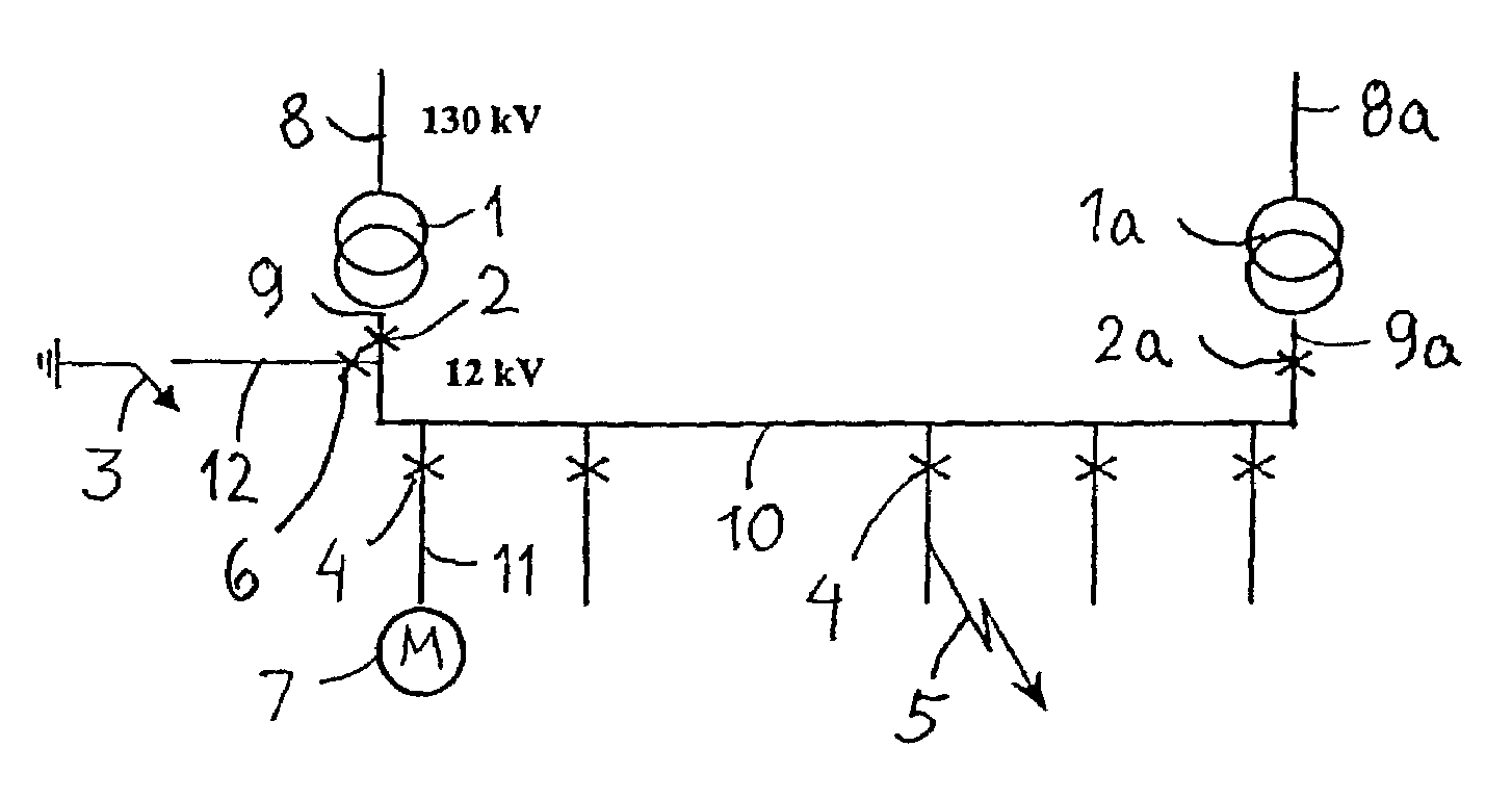
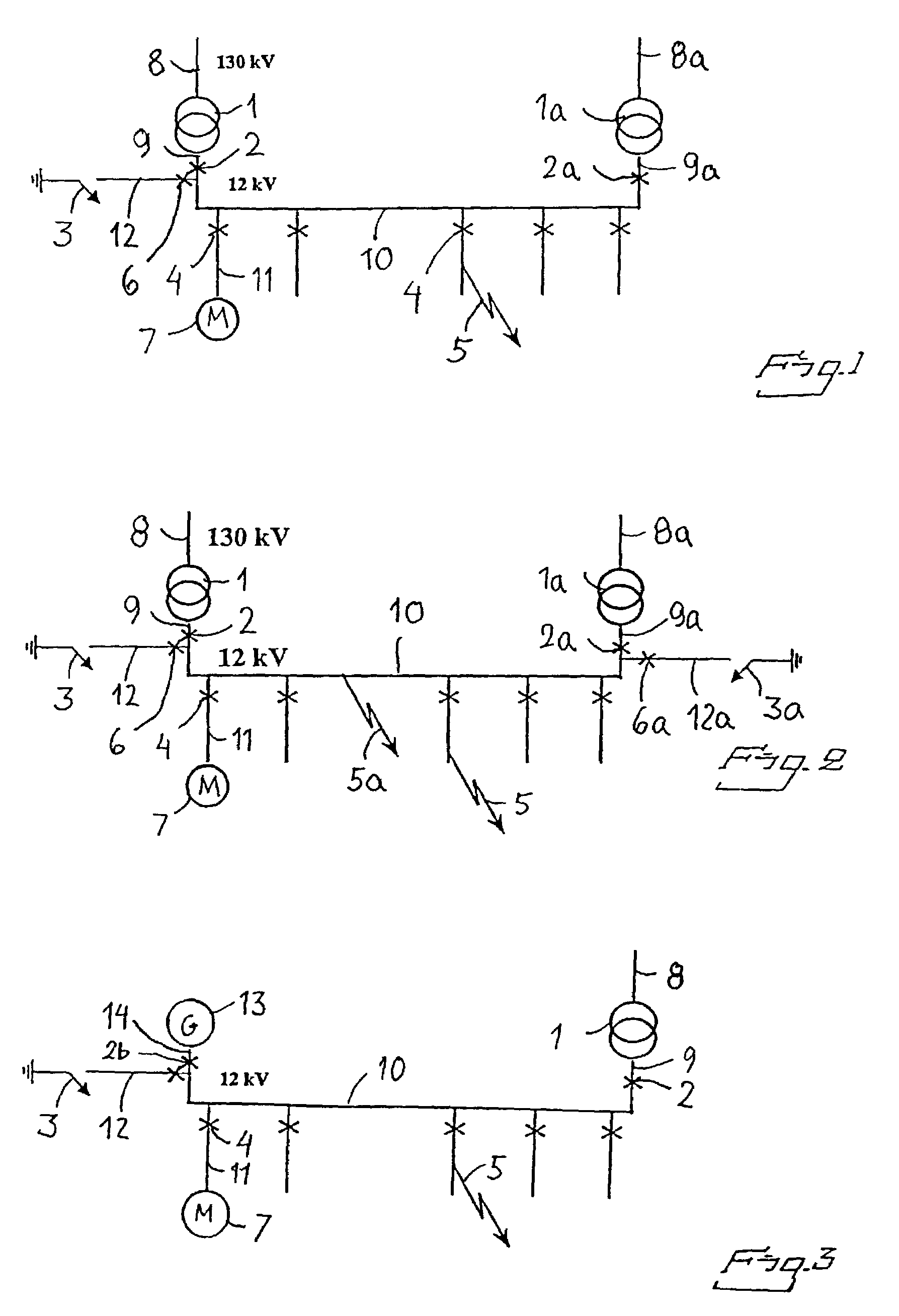
[0046]FIG. 1 shows a switchgear installation supplied with current from two different cables 8, 8a from the network, a transformer 1, 1a being arranged in each cable for step-down transformation of the voltage to the feeder cables 9, 9a. Typical voltage levels are stated for the network and switchgear installation, respectively, but these are naturally only examples. The two feeder cables 9, 9a are connected to a common busbar 10. The switchgear installation shown may either be a single switchgear installation or be formed by connecting two switchgear installations to the common busbar. Cables 11 lead from the switchgear installation to the various loads 7 in the consumer system, represented by a motor in the figure.

[0047]A breaker 2, 2a is arranged in the feeder cable 9, 9a from each transformer 1, 1a, and a breaker 4 is similarly arranged in the cable 11 to each consumer point 7. A branch cable 12 runs from the feeder cable from the transformer on the left in the figure and can di...


PUM


Abstract

An electric plant with a safety device, a method for remedying faults in a switchgear installation, and the use of a closing contact to provide security against faults. The plant includes a switchgear installation, consumer loads connected to the switchgear installation, and at least one feeder cable to the switchgear installation. The plant provides a strong consumer network that still has a high degree of safety against damage caused by short-circuiting faults. The plant includes at least two feeder cables, each connected to its own current source such as a transformer or a generator. At least one of the feeder cables is connected by a branch cable to ground. The branch cable is provided with a closing contact, which is normally open. The closing contact is arranged to be activated, i.e. to quickly close the connection to ground, in the event of short-circuiting in the switchgear installation.

Description

TECHNICAL FIELD[0001]In a first aspect the present invention relates to an electric plant with a safety device of the type described in the preamble to claim 1.[0002]In a second aspect the invention relates to a method of the type described in the preamble to claim 14, and in a third aspect to the use of a protective component in a switchgear station in accordance with claim 16.[0003]The invention is primarily intended to protect a medium-voltage switchgear installation and the electrical system and components that receive their current from the switchgear installation. It relates primarily to switchgear installations supplying a current of 12 or 24 kV but is naturally not limited to these voltage levels. The term “medium voltage” in the present application shall thus be understood to relate to the whole interval from an ordinary end user level, e.g. 127 or 220 V, up to the limit of what is generally considered to be high voltage, i.e. 72.5 kV.BACKGROUND ART[0004]Short circuits can ...

Claims


Application Information

Patent Timeline
Patent Type & Authority Patents(United States)
IPC IPC(8): H02H3/00
CPCH02H3/023H01H79/00H01H1/38H01H1/50H01H33/285
Inventor LILJESTRAND, LARS
Owner ABB TECH AG
Why Eureka
Try Eureka