Automatic ball throwing device, directing device therefor and method of making an automatic ball throwing device

a technology of automatic ball throwing and directing device, which is applied in the direction of launching weapons, sports equipment, ammunition loading, etc., can solve the problems of inability to provide an efficient method for modifying a conventional ball throwing device, and many conventional devices are limited to a narrow range of ball rotation. , to achieve the effect of improving the defensive and offensive skills of the target group, convenient handling and movement, and improving the accuracy of the target targ

US7111620B2Inactive Publication Date: 2006-09-26JOHNDREAU STEVEN S +1
21 Cites 27 Cited by

Patent Information

Authority / Receiving Office
US · United States
Patent Type
Patents(United States)
Current Assignee / Owner
Publication Date
2006-09-26
Estimated Expiration
Not applicable · inactive patent

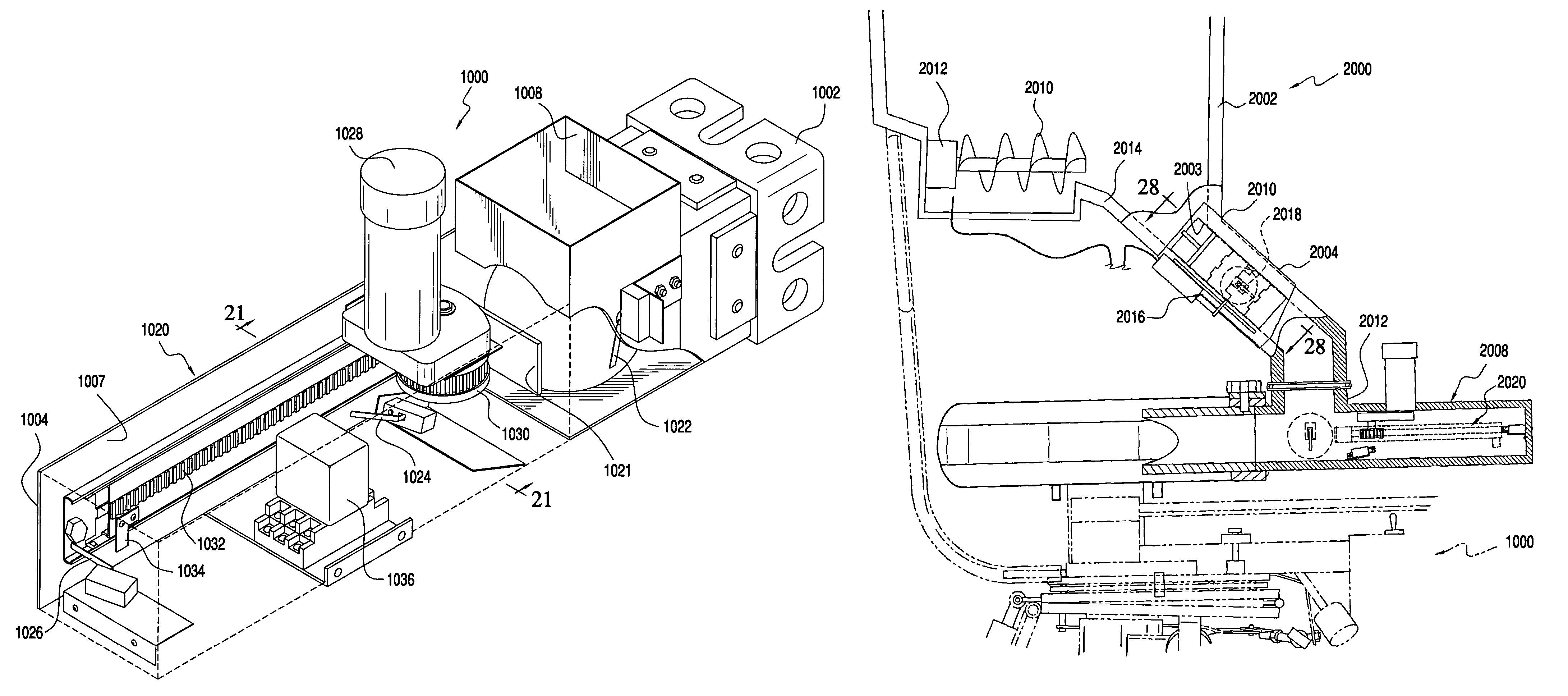
Smart Images

  • Figure 1
    Figure 1
  • Figure 2
    Figure 2
  • Figure 3
    Figure 3
Patent Text Reader

Abstract

The present invention provides a ball engagement device for use with a ball launching device, comprising a housing having first and second ends, an opening for accepting balls and a ball chamber adjacent to the opening. The device further includes a motor coupled to the housing and a pinion connected to and driven by the motor. The pinion drives a rack that has a ball engagement end, wherein the rack is slideably disposed along an interior portion of the housing. The device also includes a first switch disposed in the housing and that is operably configured to activate the motor to rotate the pinion in a first direction, the first switch is activatable by the presence of a ball in the ball chamber, a second switch disposed in the housing operably configured to rotate the pinion in an opposing second direction, a third switch disposed in the housing at a predetermined distance from the second switch and operably configured to deactivate the motor and a switch activation member disposed along the rack. Upon activation of the first switch, the motor rotates the pinion in the first direction causing the rack to push the ball out of the first end of the housing, the switch activation member travels with the housing until the activation member activates the second switch which then reverses the direction of the pinion in a second direction causing the movement of the rack towards the second end of the housing until the switch activation member strikes the third switch and turns the motor off. This invention further provides a hopper for use with the ball engagement device.
Need to check novelty before this filing date? Find Prior Art

Description

CROSS REFERENCE TO RELATED APPLICATIONS

[0001] This application is a continuation-in-part application of application Ser. No. 10 / 697,913, filed Oct. 29, 2003, which is incorporated, in its entirety, herein by reference.BACKGROUND OF THE INVENTION

[0002] 1. Field of Invention

[0003] The present invention relates to ball throwing devices.

[0004] 2. Description of Related Art

[0005] Coaches and players have used conventional ball throwing devices for years to assist in training for various sports, such as baseball and tennis. A number of such devices are described in for example, U.S. Pat. No. 6,237,583 issued to Ripley et al.; U.S. Pat. No. 5,125,653 issued to Kovács et al., and U.S. Pat. No. 6,026,798 issued to Sanders et al. However, these conventional ball throwing devices have numerous drawbacks and shortcomings.SUMMARY OF INVENTION

[0006] It is an object of the present invention to overcome the drawbacks and shortcomings of conventional ball throwing devices. Particularly, conventional ball ...

Examples

Embodiment Construction

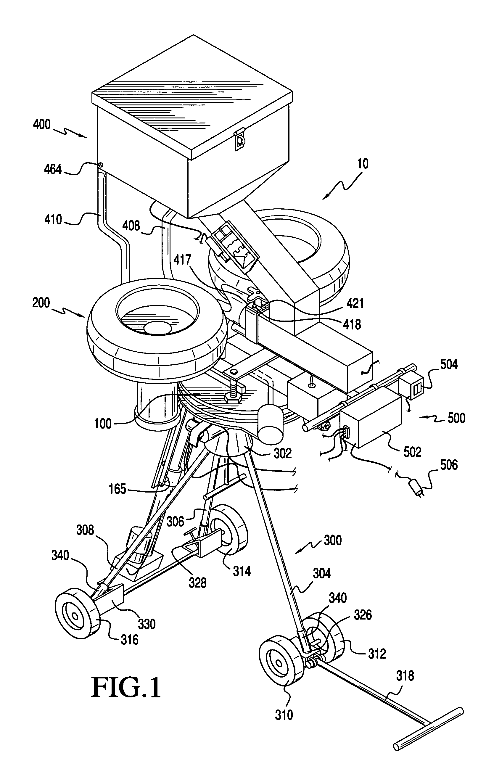
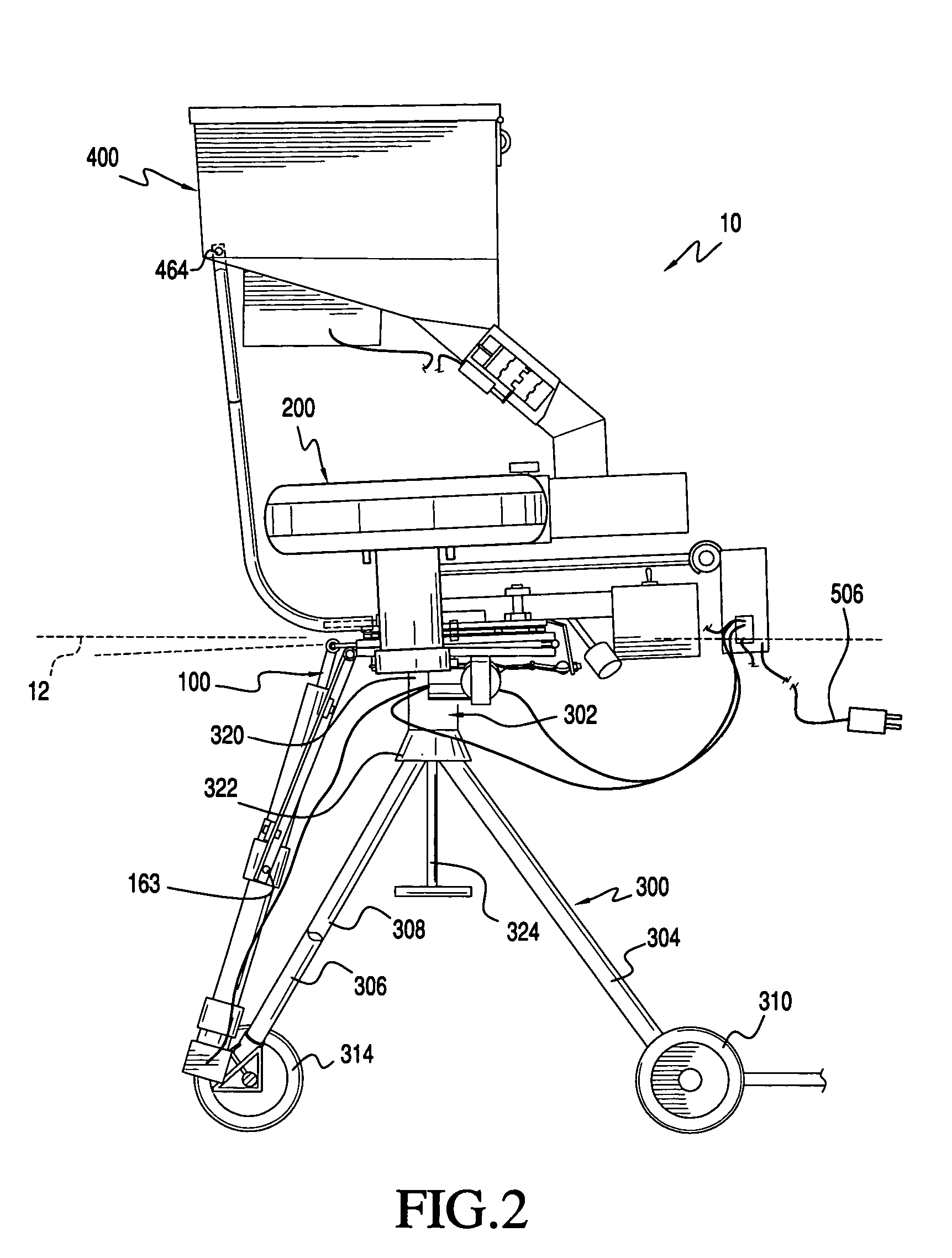
[0047]FIG. 1 shows an exemplary embodiment of an automatic ball throwing device 10 in accordance with this invention. The automatic ball throwing device 10 includes a ball directing device 100, a ball launching device 200, a support stand 300, a ball hopper 400, and a controller 500. It should be appreciated that the ball hopper 400 is optional.

[0048]The ball directing device 100 is attached to the support stand 300. The ball launching device 200 is attached to the ball directing device 100. The ball directing device 100 is operably configured to orient (i.e. rotate and / or pitch) the ball launching device 200, as will be described further below. The controller 500 is electrically connected to the ball directing device 100 and controls the aforementioned rotation and pitch of the ball launching device 200. The ball hopper 400 is attached to the ball directing device 100 and the ball launching device 200. The hopper 400 is configured to retain balls and to provide a conduit to guide b...