Automatic ball throwing device, directing device therefor and method of making an automatic ball throwing device

a technology of automatic ball throwing and directing device, which is applied in the direction of sports equipment, ammunition loading, manufacturing tools, etc., can solve the problems of inability to provide an efficient method for modifying a conventional ball throwing device, and many conventional devices are limited to a narrow range of ball rotation. , to achieve the effect of improving the defensive and offensive skills of the target team, convenient handling and movement, and improving the accuracy of the target team

Inactive Publication Date: 2005-06-09
JOHNDREAU STEVEN S +1
View PDF7 Cites 9 Cited by
  • Summary
  • Abstract
  • Description
  • Claims
  • Application Information

AI Technical Summary

Benefits of technology

[0007] The present invention provides an automatic ball throwing device that can repeatedly and accurately throw balls to a specific target or zone, throw ground balls, and launch balls through the air to various vertical and horizontal directions. The present invention allows a ball to be automatically thrown through a continuous range of ball (i.e. from a side spin about a horizontal axis of the ball through 90 degrees to a substantially forward or back spin about a vertical axis of the ball). Such a device can be used, among other things, to assist baseball players in improving their defensive and offensive skills.
[0008] The present invention is more practical and convenient than conventional ball throwing machines, because the ball throwing device of the present invention can, among other things, be utilized by a single person remote from the machine. That person can be the person practicing or a coach assisting a player. Whereas, conventional devices require an operator to be with the machine in order to control the device and throw balls in addition to the aforementioned player or coach.
[0009] Further, an embodiment of the ball throwing device of the present invention allows the device to be easily handled and moved by one person. In this way, a single coach can easily and readily move the device around the field for different applications, such as for batting and defensive practice.
[0010] Many conventional devices lack the ability to supply an adequate volume of balls to a ball launching device. For example, many conventional ball hoppers or feeders only supply a dozen or so balls. This is inefficient as a user will need to be constantly refilling the conventional hopper. The present invention provides an efficient means for maintaining an adequate bank of balls to be readily supplied to a ball launching device. This means includes a means for preventing clogging of the balls.
[0011] Many conventional pitching machines are limited in their versatility. Particularly the devices are primarily used for batting (offensive) practice. Further, altering the orientation of many conventional pitching machines is often cumbersome and it is difficult to readily attain a desired orientation. The present invention overcomes these deficiencies by providing a ball throwing device that can readily be used for offensive or defensive baseball / softball practice; (it is often desired to be able to throw a ball with not only substantially no-spin, forward spin or backward spin, but also to be able to throw a ball with side spin for defensive practice). Further, the present invention allows the orientation of the device to be readily achieved by providing automatic control of a ball directing device made in accordance with the present invention.

Problems solved by technology

Particularly, conventional ball throwing devices do not provide an efficient way to adjust the flight direction of a ball thrown by a ball launching device.
Prior devices and methods have also failed to provide an efficient method for modifying a conventional ball throwing device, (e.g., pitching machine), into an automatic ball throwing device that can automatically adjust the flight direction of a ball.
Further, many conventional devices are limited to a narrow range of ball rotation and / or do not provide for a continuous range of ball rotation through 90 degrees (i.e. from a side spin about a horizontal axis of the ball through 90 degrees to a substantially forward or back spin about a vertical axis of the ball).
This type of rotation is often not desired for baseball infield practice.
By not providing a continuous range of spin options, conventional devices do not provide realistic ball movements.

Method used


Image

  • Automatic ball throwing device, directing device therefor and method of making an automatic ball throwing device
  • Automatic ball throwing device, directing device therefor and method of making an automatic ball throwing device
  • Automatic ball throwing device, directing device therefor and method of making an automatic ball throwing device

Examples


Embodiment Construction

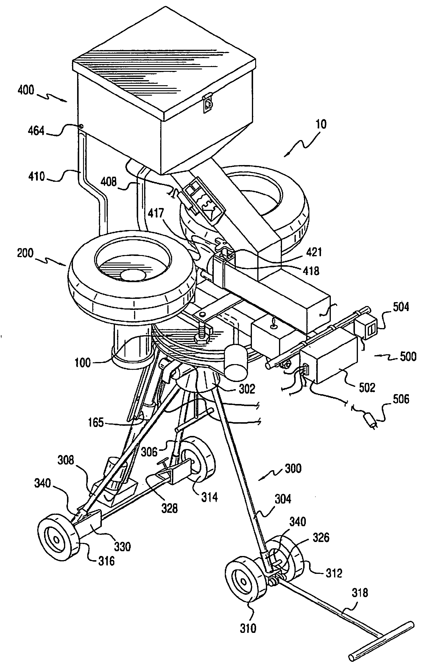
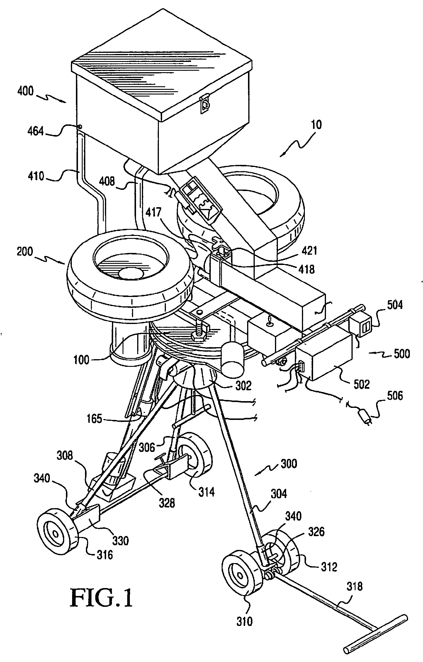
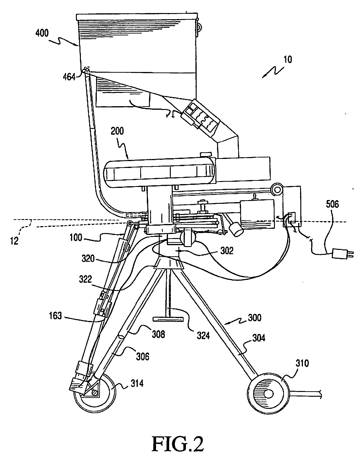
[0038]FIG. 1 shows an exemplary embodiment of an automatic ball throwing device 10 in accordance with this invention. The automatic ball throwing device 10 includes a ball directing device 100, a ball launching device 200, a support stand 300, a ball hopper 400, and a controller 500. It should be appreciated that the ball hopper 400 is optional.

[0039] The ball directing device 100 is attached to the support stand 300. The ball launching device 200 is attached to the ball directing device 100. The ball directing device 100 is operably configured to orient (i.e. rotate and / or pitch) the ball launching device 200, as will be described further below. The controller 500 is electrically connected to the ball directing device 100 and controls the aforementioned rotation and pitch of the ball launching device 200. The ball hopper 400 is attached to the ball directing device 100 and the ball launching device 200. The hopper 400 is configured to retain balls and to provide a conduit to guide...


PUM


Abstract

The present inventions provides a method of modifying a pitching machine, including obtaining a pitching machine have a ball launching device and a support stand, removing the ball launching device from the support stand; attaching a directing device to the support stand, and attaching the ball launching device to the directing device. The present invention also provides methods of making an automatic ball throwing devices.

Description

CROSS REFERENCE TO RELATED APPLICATION [0001] This application is a divisional application of U.S. application Ser. No. 10 / 697,913, filed on Oct. 29, 2003, which is incorporated, in its entirety, herein by reference.BACKGROUND OF THE INVENTION [0002] 1. Field of Invention [0003] The present invention relates to ball throwing devices. [0004] 2. Description of Related Art [0005] Coaches and players have used conventional ball throwing devices for years to assist in training for various sports, such as baseball and tennis. A number of such devices are described in for example, U.S. Pat. No. 6,237,583 issued to Ripley et al.; U.S. Pat. No. 5,125,653 issued to Kováacs et al., and U.S. Pat. No. 6,026,798 issued to Sanders et al. However, these conventional ball throwing devices have numerous drawbacks and shortcomings. SUMMARY OF INVENTION [0006] It is an object of the present invention to overcome the drawbacks and shortcomings of conventional ball throwing devices. Particularly, convent...

Claims


Application Information

Patent Timeline
Patent Type & Authority Applications(United States)
IPC IPC(8): A63B69/40F41A9/03F41B4/00F41B11/02
CPCA63B69/406A63B2069/402F41A9/03F41B4/00Y10T16/18F41B11/53Y10T16/205Y10T16/203F41B11/57
Inventor JOHNDREAU, STEVEN S.JOHNDREAU, DAVID E.
Owner JOHNDREAU STEVEN S
Why Eureka
Try Eureka