Box light

a box light and light technology, applied in outdoor lighting, electric lighting without self-contained power, protection devices for lighting, etc., can solve the problems of adversely affecting their portability, and achieve the effect of preventing lamp breakage, being portable and durable for transportation

Inactive Publication Date: 2006-10-17
REMPEL LEE W
View PDF6 Cites 68 Cited by
  • Summary
  • Abstract
  • Description
  • Claims
  • Application Information

AI Technical Summary

Benefits of technology

[0015]In one embodiment the first hinge further includes means for selectively angularly positioning the clamshell-halves relative to one another about the first hinge. For example, the means for angularly positioning may include a selectively actuable latch or other means for selectively locking the included angle at least at substantially 135 degrees, one hundred eighty degrees or two hundred seventy degrees. To facilitate pivoting the clamshell-halves more than one hundred eighty degrees about the first hinge so as to fold the clamshell-halves into a two hundred seventy degree, or more, back-to-back open position, advantageously the ends of the housing adjacent the first hinge are sloped or inclined faces, for example, sloped or inclined so as to form an angle of forty five degrees between the sloped or inclined faces and the corresponding lamp face of the corresponding clamshell-half. Thus, with the clamshell-halves in the two hundred seventy degree open position, with the inclined faces inclined at substantially forty five degrees, the inclined faces are abutting or closely adjacent so that the inclined faces limit the pivoting of the clamshell-halves about the first hinge.
[0017]A proximity sensor may advantageously be provided for sensing when the first and second clamshell-halves are substantially in the closed position and, in response, for shutting off electrical power to the lamps whereby the lamps will not be left on when the housing is closed.

Problems solved by technology

It is known that when using many of these temporary portable light sources that they often cannot be maintained in adequate position, and / or are vulnerable to damage during transportation, which adversely affects their portability.

Method used


Image

  • Box light
  • Box light
  • Box light

Examples


Embodiment Construction

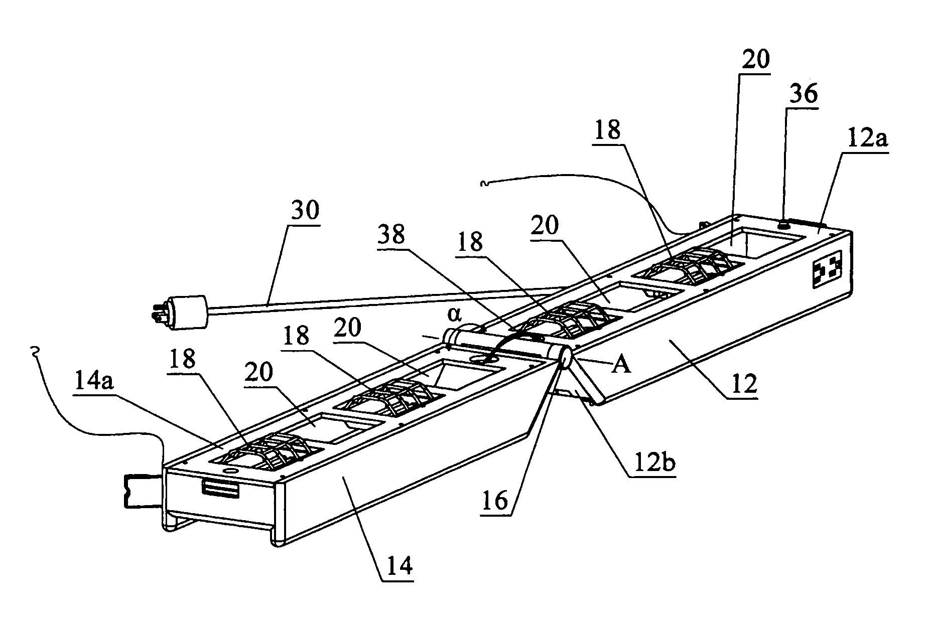
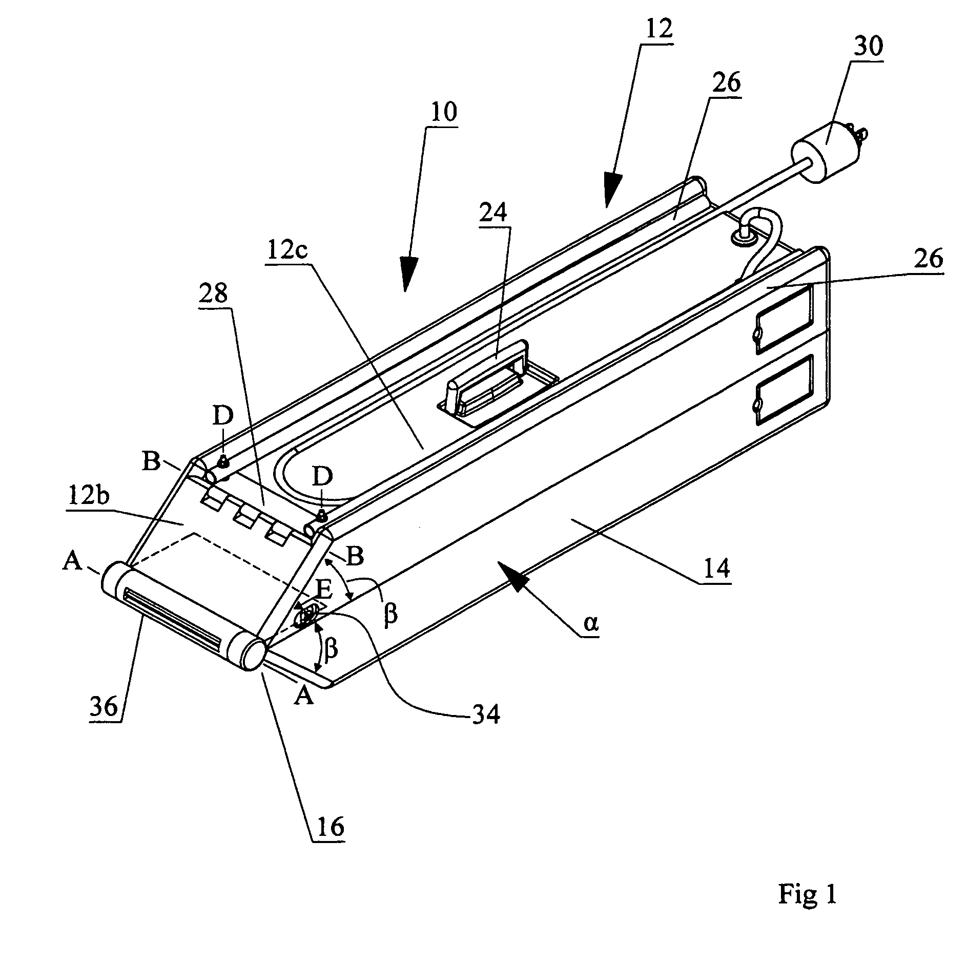
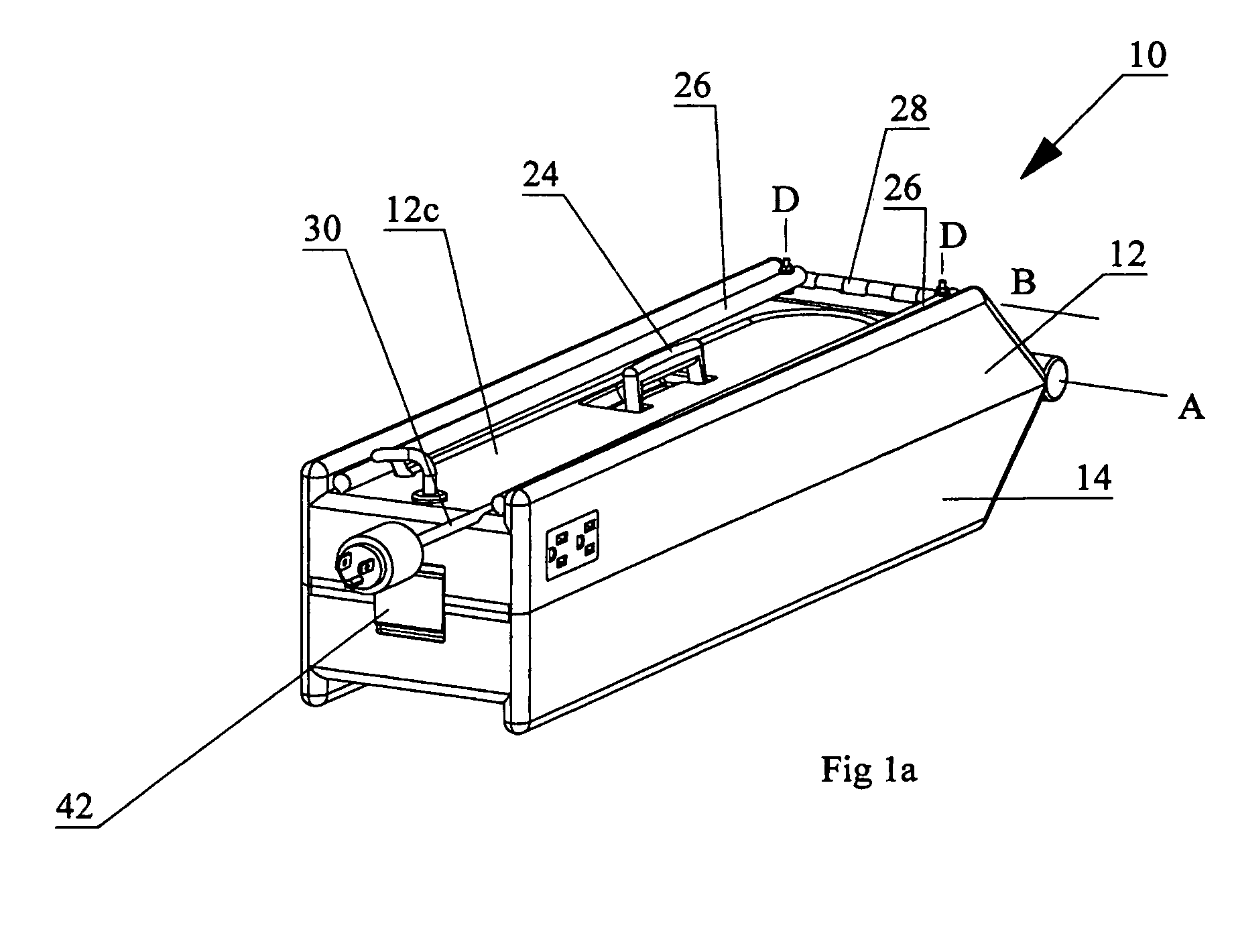
[0035]With reference to the drawings, wherein similar characters of reference denote corresponding parts in each view, the present invention may be characterized as a self-contained, clamshell-opening, portable box light 10. Box light 10 has two clamshell-halves 12 and 14 mounted to one another about a common first hinge 16 so that the two halves open and close about the hinge. When the two halves are in the closed position of FIG. 1, the planar lamp faces 12a and 14a of the halves are closed together in opposed facing relation so as to nest, or at least align, the lights on one clamshell-half with corresponding apertures on the opposed facing clamshell-half. Because the light cages 18 protrude from the planar lamp faces 12a and 14a of the corresponding halves 12 and 14, and because cages 18 mate into corresponding apertures 20 in the opposed facing opposite clamshell-half, the volume of the box light housing may be minimized for ease of transportation and storage. Apertures 20 also...


PUM


Abstract

A box light includes a housing having first and second clamshell-halves. Each clamshell-half has a lamp face and an opposite exterior surface. At least one lamp and its corresponding protective enclosure is mounted in each of the lamp faces. Each of the lamp faces has at least one lamp-receiving aperture. The clamshell-halves are rotatably mounted to one another by a first hinge for rotation relative to another about the first hinge between open and closed positions. The open position includes selectively positionable open positions exposing the lamp faces so that an included angle between the lamp faces may be opened to two hundred seventy degrees whereby the lamps on each lamp face shines outwardly and oppositely of the housing when electrically powered. In the closed position the lamp faces are in closely adjacent opposed facing relation and the exterior surfaces are oppositely disposed. Also, when in the closed position, the at least one lamp and its protective enclosure on each of the first and second clamshell-halves is aligned and mated with the lamp-receiving aperture on the opposed facing lamp faces so as to insert at least the protective enclosure of each of the at least one lamps into mating engagement with the corresponding lamp-receiving apertures in the opposed facing lamp faces.

Description

CROSS REFERENCE TO RELATED APPLICATIONS[0001]This application claims priority from U.S. Provisional Patent Application No. 60 / 548,421 filed Mar. 1, 2004 entitled Box Light.FIELD OF THE INVENTION[0002]This invention relates to portable lighting systems that are rugged and adaptable to general work lighting applications primarily in construction, temporary service and maintenance.BACKGROUND OF THE INVENTION[0003]Adequate work lighting in construction, service, or maintenance applications is necessary for a safe effective working environment. The conventional so-called “trouble light”, that is, an incandescent bulb protected by and mounted within a cage, has been a mainstay of temporary indoor work lighting for years. More recently stand-supported quartz halogen work lamps, and variations of stand-supported fluorescent work lamps have become common.[0004]It is known that when using many of these temporary portable light sources that they often cannot be maintained in adequate position,...

Claims


Application Information

Patent Timeline
Patent Type & Authority Patents(United States)
IPC IPC(8): F21V21/14F21L14/00F21L14/02F21V1/00F21V15/01F21V15/02F21V21/06F21V21/30
CPCF21L14/02F21V17/007F21V21/06F21V21/30F21V15/02F21W2131/1005
Inventor REMPEL, LEE W.
Owner REMPEL LEE W
Why Eureka
Try Eureka