Slag transport and dumping apparatus and method

a technology of dumping apparatus and slag, which is applied in the direction of transportation items, blast furnace components, blast furnaces, etc., can solve the problems of requiring a great amount of care for handling such materials, causing great harm, injury, and even death to persons coming into contact, and a bit of problematic to safely dispose of such by-products

Active Publication Date: 2011-08-09
PALING TRANSPORTER
View PDF3 Cites 5 Cited by
  • Summary
  • Abstract
  • Description
  • Claims
  • Application Information

AI Technical Summary

Benefits of technology

[0026]According to an aspect of one preferred embodiment of the invention, a dumping angle may preferably, but need not necessarily, be defined between the dump container and the pallet support frame. The outside portion of the dump container may preferably, but need not necessarily, be provided with at least one lift arm locking member. The link end portion of the lift arm may preferably, but need not necessarily, be provided with a container locking extension that engages the lift arm locking member in the slag pouring configuration, so as to restrict pivoting of the dump container beyond a predetermined maximum value for the dumping angle.
[0045]According to an aspect of one preferred embodiment of the invention, a dumping angle may preferably, but need not necessarily, be defined between the dump container and the pallet support frame. The outside portion of the dump container may preferably, but need not necessarily, be provided with at least one lift arm locking member. The link end portion of the lift arm may preferably, but need not necessarily, be provided with a container locking extension that engages the lift arm locking member in the slag pouring configuration, so as to restrict pivoting of the dump container beyond a predetermined maximum value for the dumping angle.

Problems solved by technology

In the past, it has been somewhat problematic to safely dispose of such by-products.
In any event, slag may heretofore have caused great harm, injury, and even death to persons coming into contact therewith.
Of course, any handling of such materials may also have required a great amount of care, with a concomitant and costly expenditure of time and effort.
The aforesaid frusto-conical shaping of prior art slagpots may have been generally undesirable, insofar as it may have contributed to an inherent instability in the slagpots which may have been prone to tipping and the like—an exceedingly dangerous occurrence when dealing with very high temperature slag.
Again, the use of such supporting structures may have tended to subject such structures, and any associated human operators, to significant harm and / or damage.
In addition, prior art slagpots may have been at risk of exploding when filled with high temperature slag.
Such explosions may also have previously caused, for example, damage to expensive equipment, and emergency shutdowns of facilities (and the loss of productivity associated with the subsequent downtime).
These likelihood of such possibilities, and the risk of serious injury or death, may be generally thought to increase in dependent relation upon the amount of slag contained in the slagpot, generally rising with the use of higher capacity slagpots.
Prior art multi-stage processes of this general type may have entailed a large number of handling steps and may have required that the slag remain in the slagpots for a significant length of time.
It is also possible that, when slag remains in a slagpot for a significant duration, the risk of explosion (and / or container failure to retain the slag) may increase.
In addition, a greater number of moves between multiple locations may heretofore typically have involved more handling steps, possibly increasing the risk of spillage, explosion, and / or other potentially catastrophic incidents.
In some instances, these arms may have been prone to breakage and / or melting under the stress and / or heat from the loaded slagpots.
Such dedicated vehicles may also have tipped and / or become unstable whilst loading and / or moving the filled slagpot.
Again, such unfortunate incidents could result in any one or more of the many dire consequences discussed above.
Unfortunately, such designs sacrifice stability and may lead to an increased risk of spillage of high temperature slag from the slagpots transported by such transport vehicles.
In particular, articulated units may have had a tendency to become unbalanced, thereby increasing the potential for spillage and / or other incidents.
This risk may have been increased by the aforementioned instability of the slagpots themselves.
Articulated transport vehicles of this general type (and / or any transport vehicle that exhibits a high degree of instability) may have also been known to encounter serious difficulties at the dumping location, upon attempting to expel or release the high temperature slag from the carried slagpot.
That is, in attempting, for example, a controlled tipping or inversion of the slagpot, so as to allow release of the slag therefrom, the transport vehicle may have itself been at risk of tipping.
Parts of the transport vehicle may also have been subject to failing under the stress of the loaded slagpot.
In either case, the results may heretofore have been catastrophic, particularly for the operator of the transport vehicle, and / or any persons or equipment located proximal to the dump location.
In addition, if any problems did occur with the prior art transport vehicles, subsequent to receipt of the slagpot thereon, it may heretofore have been exceedingly difficult (and / or impossible) to remove the slagpot therefrom, such that the slag therein may thereafter have solidified.
In such instances, much time could be lost both in dealing with the issue of the hardened slag, and in repairing and / or replacing the transport vehicle itself.

Method used


Image

  • Slag transport and dumping apparatus and method
  • Slag transport and dumping apparatus and method
  • Slag transport and dumping apparatus and method

Examples


Embodiment Construction

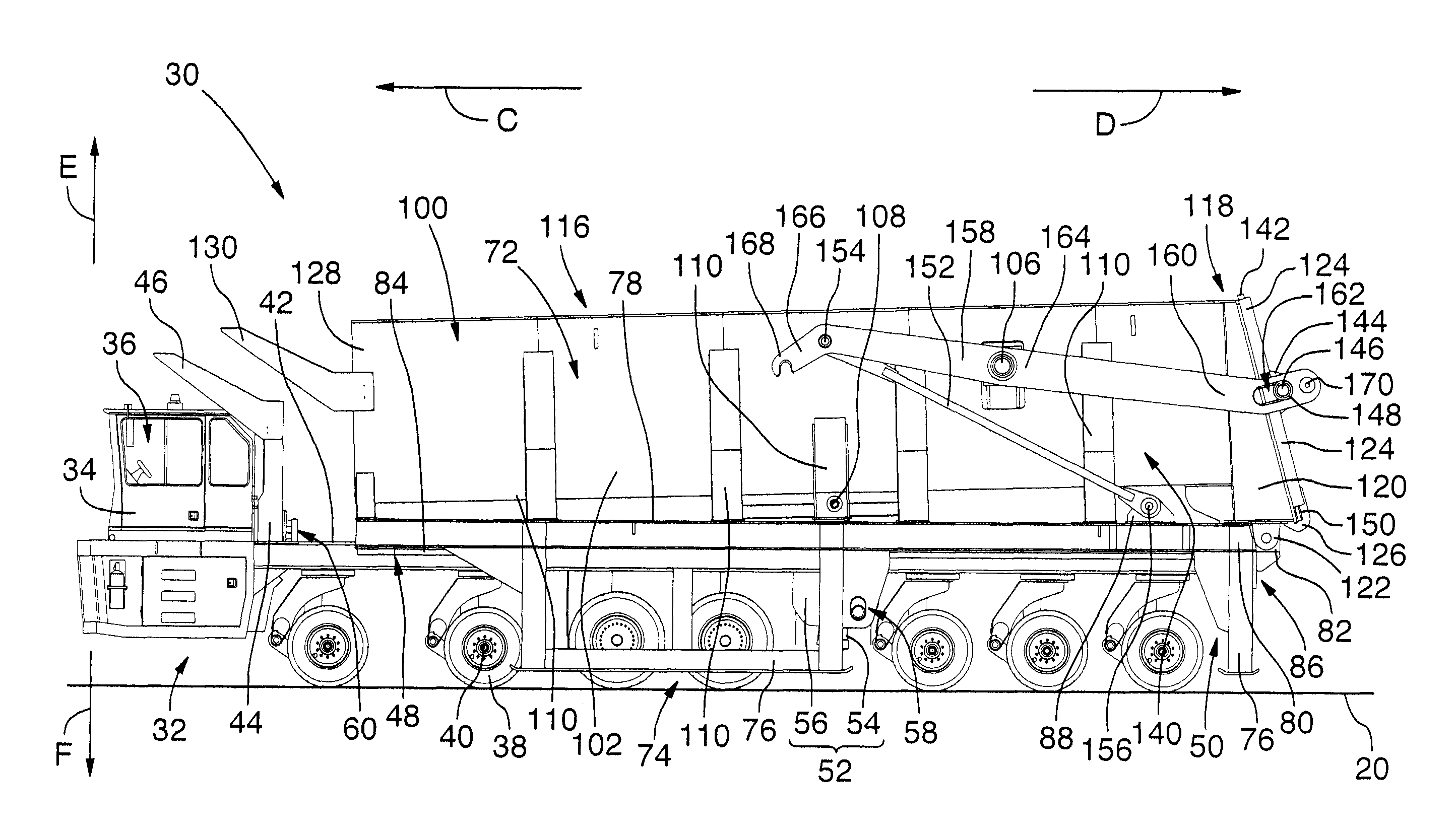
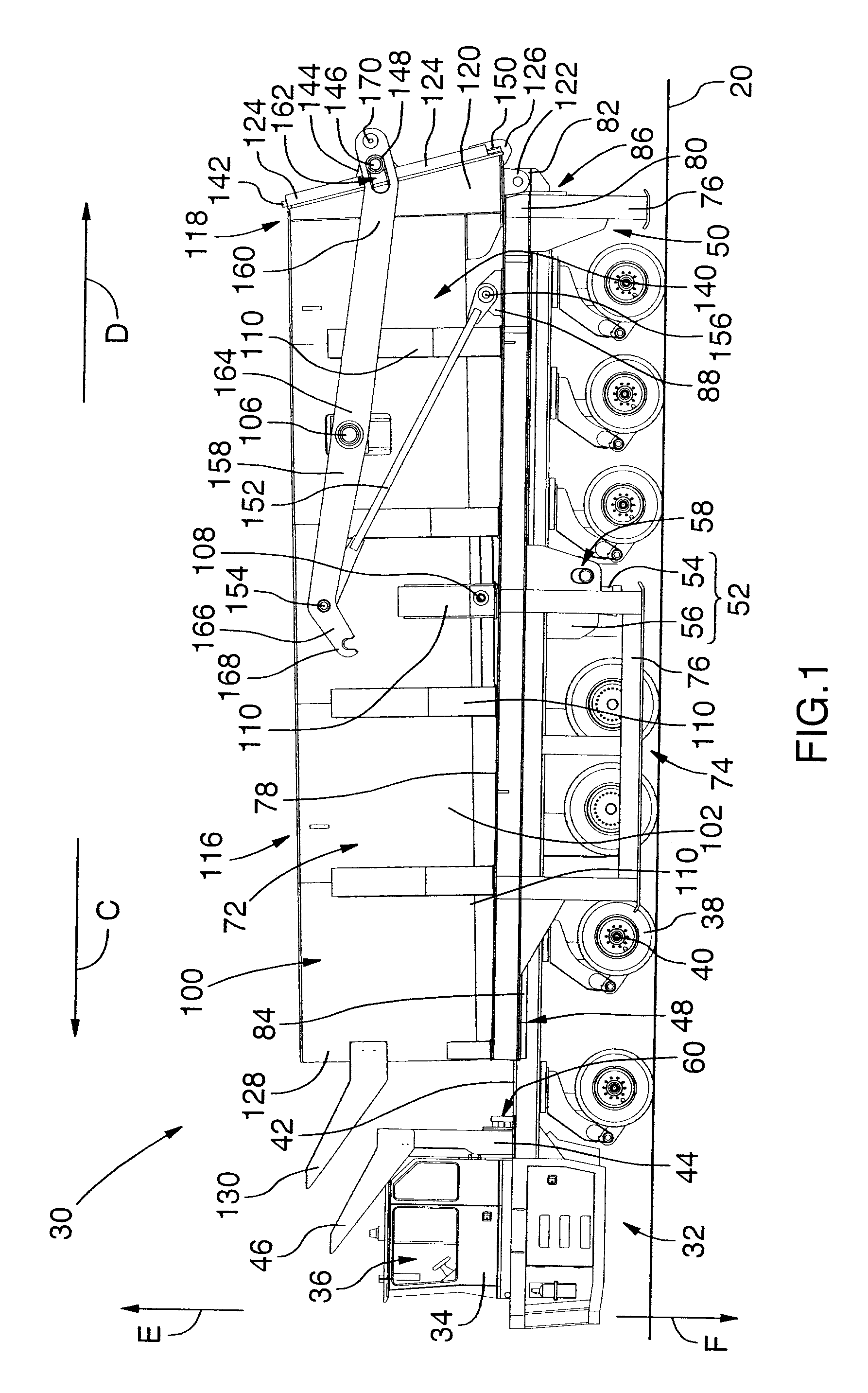
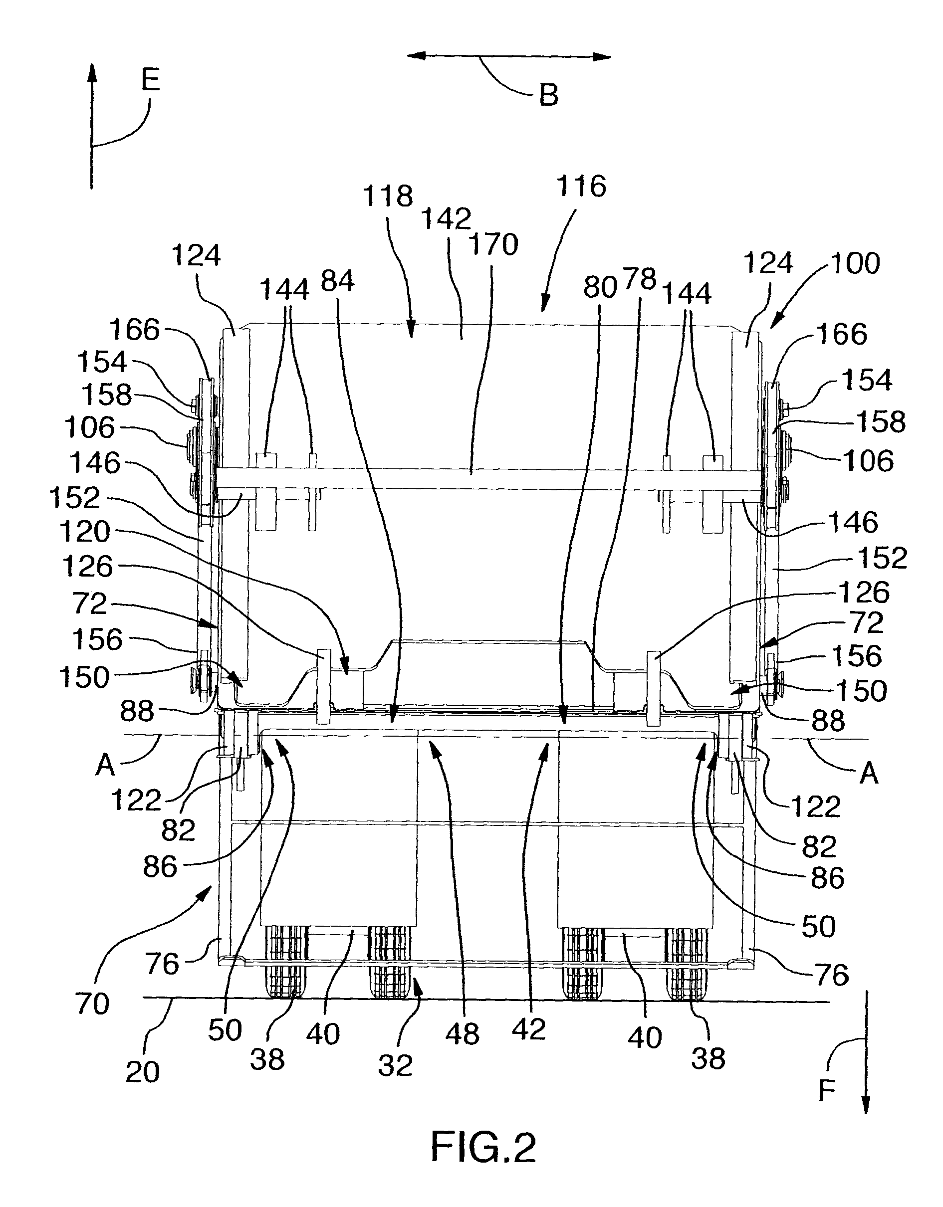
[0075]Referring now to FIGS. 1 and 2 of the drawings, there is shown a slag transport and dumping apparatus 30, according to a preferred embodiment of the invention, which may be used to transport high temperature slag 22 over the ground 20 from a steel making furnace (not shown) to a slag dumping area (not shown). The apparatus 30 includes a transport vehicle 32, a pallet 70, and a container lifting mechanism 52.

[0076]The transport vehicle 32 includes a front cab portion 34, wheels 38, and a rear transport bed 42. The front cab portion 34 substantially encloses an interior seating compartment 36 which is preferably sized to accommodate a driver (not shown). The wheels 38 are supported on axles 40 and are adapted to rollably engage the ground 20. As best shown in FIG. 7, the rear transport bed 42 includes a front bed wall 44 and a pallet interface portion 48. The front bed wall 44 is preferably provided with a cab awning 46 that extends at least part-way over the front cab portion 3...


PUM

PropertyMeasurementUnit
dumping angleaaaaaaaaaa
temperatureaaaaaaaaaa

Abstract

A slag transport and dumping apparatus, for use with slag, includes a vehicle, a pallet, and a lifting mechanism. The vehicle includes a bed having a pallet interface. The pallet includes a support frame having ground support members, and a transporter interface selectively engaging the pallet interface. A dump container has a slag reservoir. Rear pivots on the container and pallet, together with the lifting mechanism, which is securely mounted to the bed of the vehicle and selectively engages the container, enable secure selective pivoting of the container between slag retaining and pouring configurations. In a loading configuration, the reservoir receives the slag, the container is in the retaining configuration, and the vehicle is removed from the pallet. In a transporting configuration, the container is in the retaining configuration, and the vehicle securely engages the pallet, in carrying relation, thus enabling transport of the pallet.

Description

FIELD OF THE INVENTION[0001]The present invention relates to a slag dumping apparatus, and more particularly, to a slag transport and dumping apparatus and method for use in transporting high temperature slag over ground from a steel making furnace to a slag dumping area.BACKGROUND OF THE INVENTION[0002]In the metal refining and processing industry, among others, high temperature by-products are frequently produced. In the past, it has been somewhat problematic to safely dispose of such by-products.[0003]Slag is just one example of a high temperature by-product that is produced during the processing of metals, such as, for example in steel-producing furnaces. When slag is removed from these furnaces (e.g., for disposal), it may typically be at a temperature in the approximate order of about 1100 degrees Celsius (° C.)—though the precise temperature may vary depending on the exact processes and furnaces owing to its formation, and / or on the materials used in such furnaces. In any eve...

Claims


Application Information

Patent Timeline
Patent Type & Authority Patents(United States)
IPC IPC(8): C21B3/10
CPCB60P1/16B60P1/26B60P1/28B60P1/286C21B3/10C21B2400/07
Inventor CHARCZUK, BOGDAN Z.EVANS, JOHN L.
Owner PALING TRANSPORTER
Why Eureka
Try Eureka