Closer arm assembly for an automatic door closer

a technology for closing arms and door closers, which is applied in the direction of door/window fittings, multi-purpose tools, construction, etc., can solve the problems of only limited resistance to shear stress, unsatisfactory banging noise, and failure of tension pins, so as to limit relative pivoting of arms and suppress noise

Active Publication Date: 2008-11-04
DORMAKABA DEUT GMBH
View PDF11 Cites 4 Cited by
  • Summary
  • Abstract
  • Description
  • Claims
  • Application Information

AI Technical Summary

Benefits of technology

[0010]The closer arm assembly according to the invention includes a main arm having a first end and a second end, wherein the first end can be fixed to the output shaft so that the main arm pivots when the output shaft rotates; a connecting arm having a first end and a second end, wherein the first end of the connecting arm is pivotably connected to the main arm and the second end of the connecting arm can be pivotably connected to the other of the door and the jamb; and a stop which contacts the connecting arm to limit relative pivoting of the arms. The stop is provided with a cushion that suppresses noise as the connecting arm contacts the cushion. In a bumper type stop mounted to a soffit plate, this cushion may be a UHMW (ultra high molecular weight) nylon button on the end of the spring which is hit by the connecting arm. In a stop at the elbow joint between the main arm and the connecting arm, the cushion may be a urethane sleeve which is fitted on a cylinder mounted for rotation at the second end of the main arm.
[0011]The invention also relates to a hold open device that includes a housing fixed to the connecting arm, a plunger extending from the housing for sliding movement through a hole in the connecting arm and into engagement with an engaging feature, a detent which engages the plunger, a hold open spring which loads the detent against the plunger so that the closer cannot automatically close the door when the plunger engages the engaging feature and the hold open spring is compressed, and a release which reduces compression of the hold open spring so that the closer can disengage the plunger from the engaging feature.
[0014]In an embodiment having a stop at the elbow, damping of the final stage of opening movement may be provided by a slide track fixed to the door jamb, a shoe which can slide in the track and to which the second end of the connecting arm is pivotably connected, and a spring which can be compressed by the shoe after the stop prevents further relative pivoting of the arms. This arrangement reduces the stress on the stop at the elbow.
[0015]The features according to the invention not only reduce noise which results when a door is abruptly opened so that the connecting arm hits the stop, but reduce the stress on components such as the mounts for the stop.

Problems solved by technology

Known bumpers do not have any cushioning at the contact point with the connecting arm, which results in an undesirable banging noise when the connecting arm hits the bumper.
This permits the housing to pivot, but provides only limited resistance to shear stress.
Here the tension pin is subject to failure by repeated tensile stress.
Here too an undesirable banging occurs when the connecting arm hits the stop.

Method used


Image

  • Closer arm assembly for an automatic door closer
  • Closer arm assembly for an automatic door closer
  • Closer arm assembly for an automatic door closer

Examples


Embodiment Construction

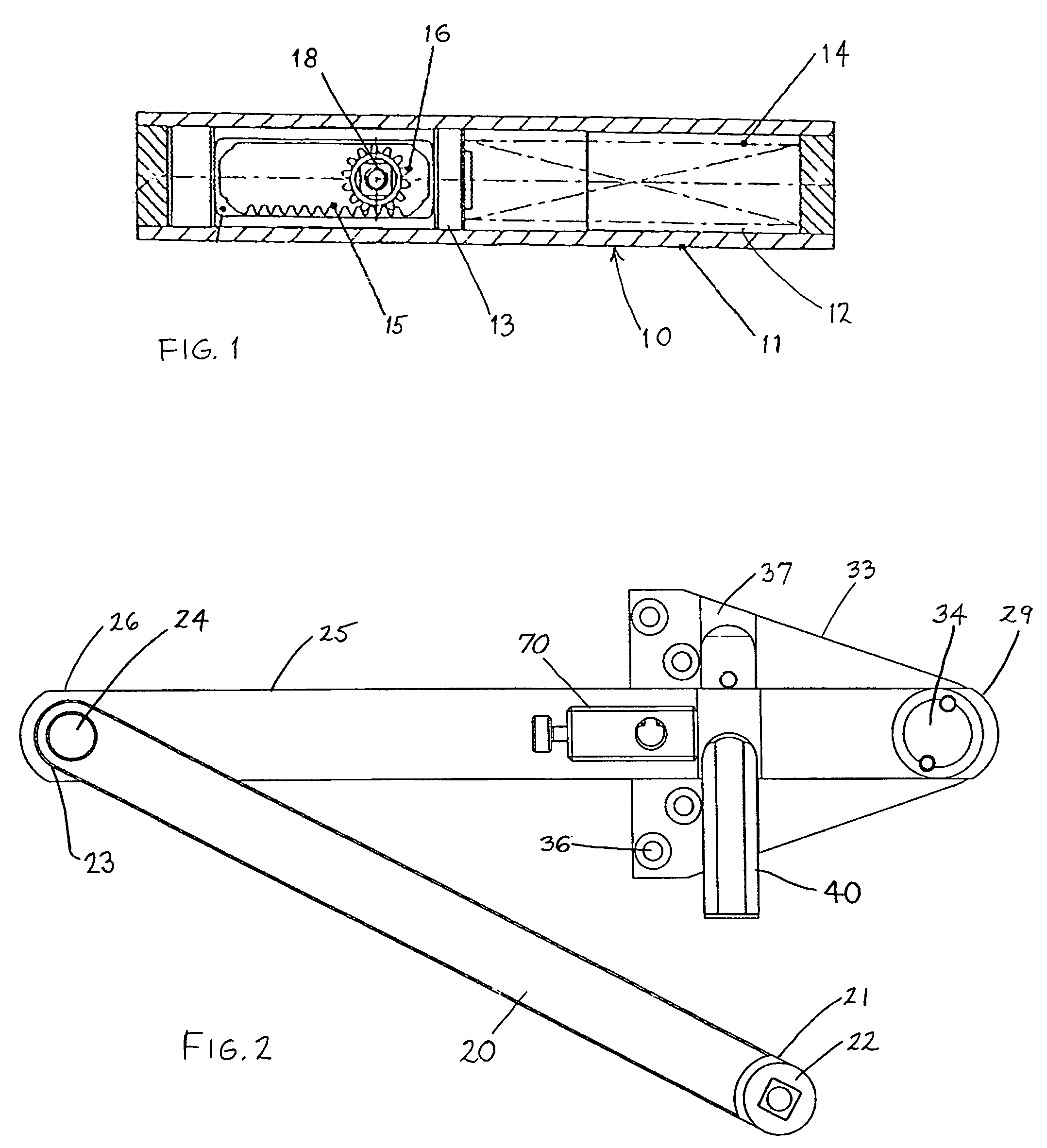
[0027]The closer arm assembly according to the present invention is designed for use with an automatic door closer of the type shown in cross section in FIG. 1, wherein the closer 10 includes a housing 11 having a cylinder 12 which receives a piston 13. The piston 13 is acted on by closing spring 14 on one side and incorporates a rack 15 on the other side that turns a pinion 16. The pinion 16 is fixed to an output shaft 18 that is journaled in the housing 11 and provides the torque for pivoting an arm to close the door. Other features, such as hydraulic lines and valves that regulate the speed of opening and closing the door, are not germane to the invention and are not shown or further described. Other designs of door closer may also be used with the invention, so long as they include the feature of an output shaft that provides torque to close the door.

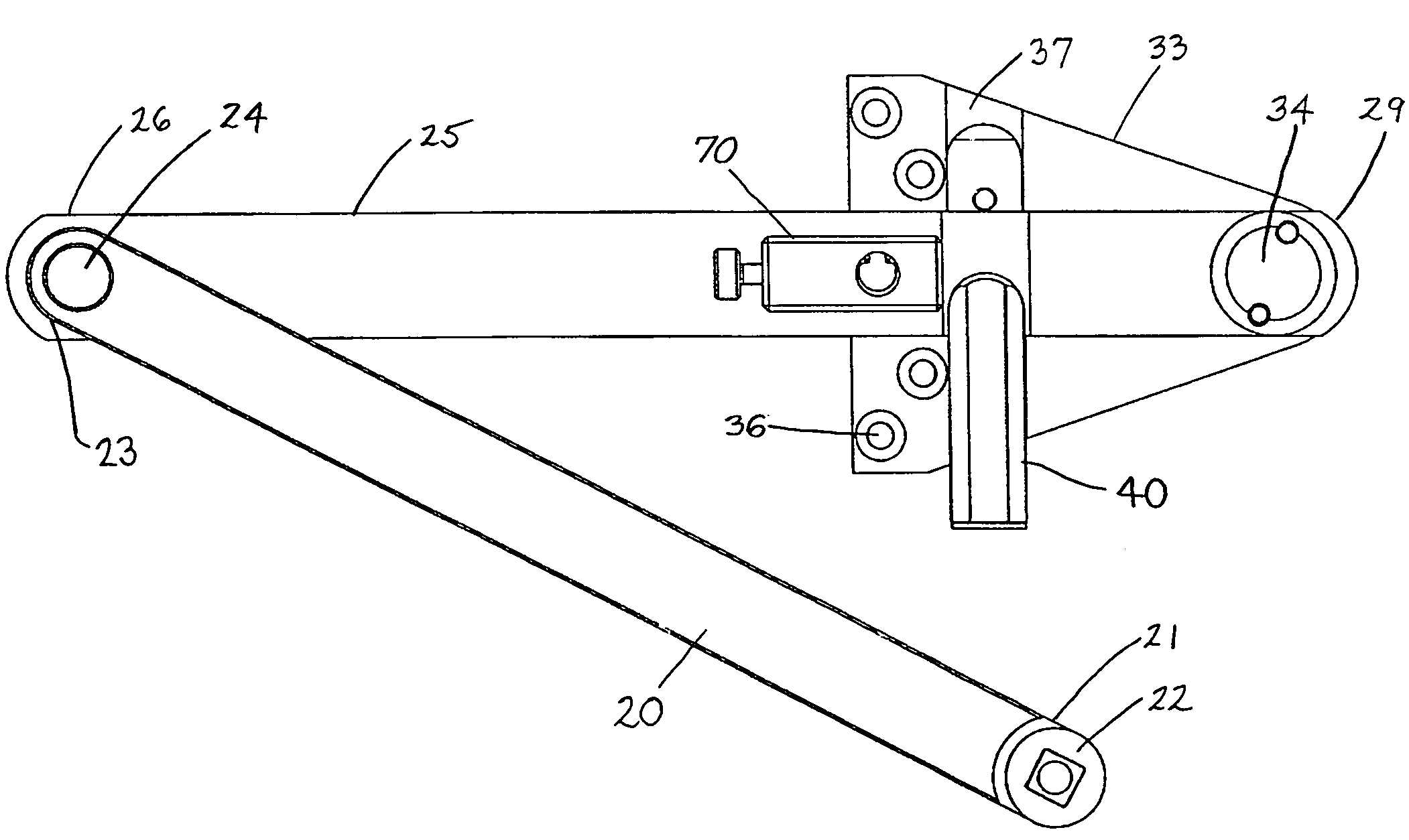
[0028]FIG. 2 shows a closer arm assembly including a main arm 20 having a first end 21 and an opposed second end 23. The first end...


PUM


Abstract

Closer arm assembly includes a main arm having a first end fixed to the output shaft of a closer fixed to one of a door and a door jamb so that the main arm pivots when the output shaft rotates, and a connecting arm having a first end pivotably connected to the main arm and a second end connected to the other of the door and the door jamb. The connecting arm contacts a stop to limit relative pivoting of the arms, the stop including a cushion with a contact surface which suppresses noise as the connecting arm contacts the cushion. The stop can be in the form of a spring loaded bumper fixed to a soffit plate, or a pin fixed to the second end of the main arm. A hold open device can be fixed to the connecting arm for engaging a feature on either the soffit plate or the main arm, the hold open device having a spring loaded detent which is released by manually turning a knob.

Description

BACKGROUND OF THE INVENTION[0001]1. Field of the Invention[0002]The invention relates to closer arm assembly for a door closer that automatically closes a door hinged to a door jamb, the closer being mounted to one of the door and the door jamb and including an output shaft that rotates to load a spring when the door is opened, the loaded spring providing the motive force for closing the door.[0003]2. Description of the Related Art[0004]Automatic door closers are well known, and typically include a housing which can be mounted to one of the door and the jamb, a piston in the housing, a closer spring which acts on the piston, an output shaft which rotates as the piston moves, and hydraulic channels and valves that regulate the closing movement. The rotation of the output shaft is typically translated to linear movement of the piston by a rack and pinion arrangement. An example is disclosed in U.S. Pat. No. 6,618,899.[0005]Closer arm arrangements include both single arm and double arm...

Claims


Application Information

Patent Timeline
Patent Type & Authority Patents(United States)
IPC IPC(8): E05F3/00
CPCE05F3/102E05F3/22E05F3/221Y10T16/577Y10T16/287Y10T16/27E05Y2900/132E05Y2201/624
Inventor MCKINNEY, PATRICKBEATON, TODD S.LINDEMUTH, B. BRIANWHITCOMB, GERALD R.
Owner DORMAKABA DEUT GMBH
Why Eureka
Try Eureka