

Hand tool having an adjustable head with joint lock mechanism
a technology of joint lock mechanism and adjustable head, which is applied in the direction of screwdrivers, manufacturing tools, wrenches, etc., can solve the problems of reducing the life of hand tools, loose local structure, and inability to properly position, so as to achieve convenient and secure positioning
- Summary
- Abstract
- Description
- Claims
- Application Information
AI Technical Summary
Benefits of technology
Problems solved by technology
Method used
Image

Examples
Embodiment Construction
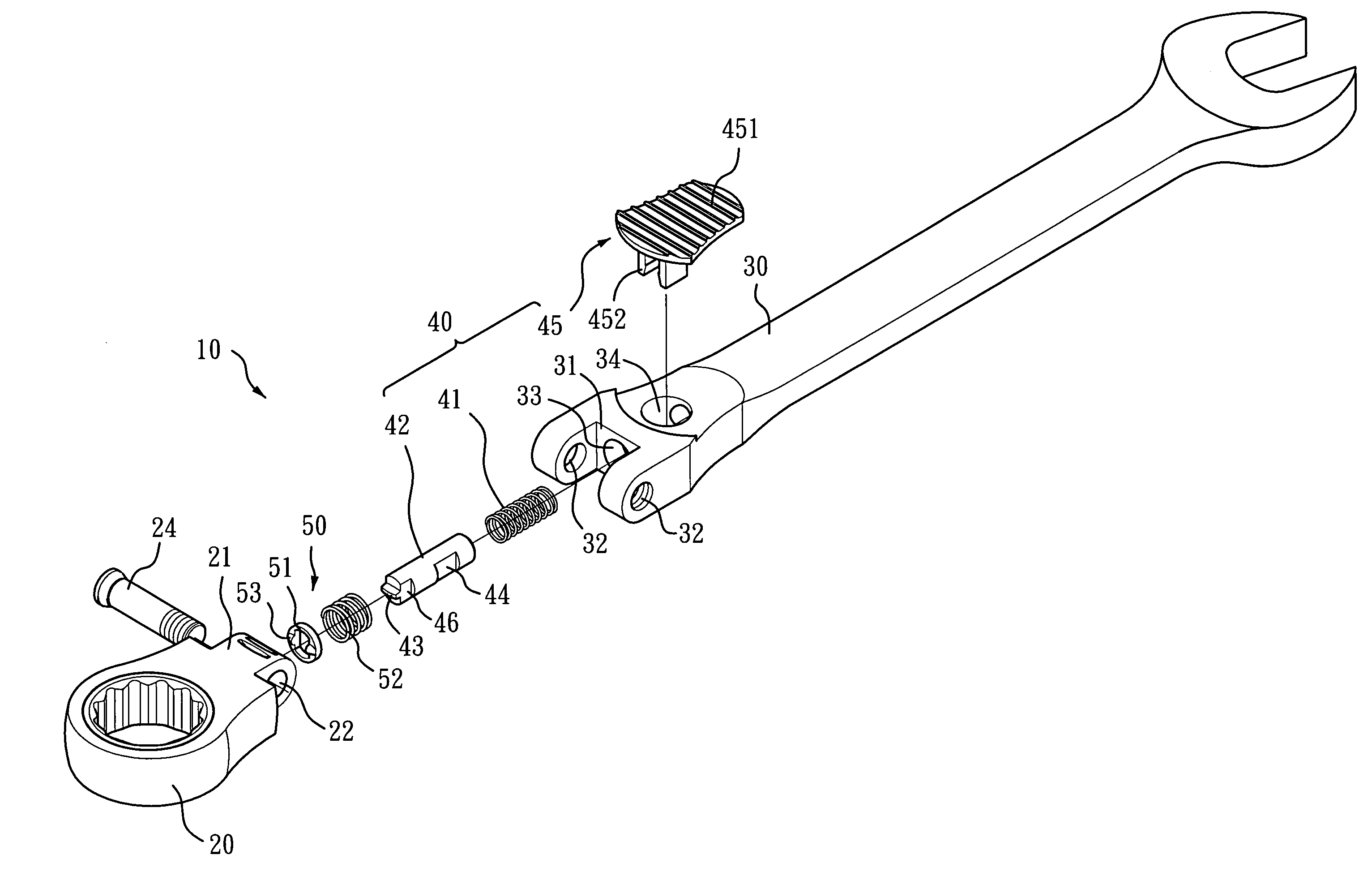
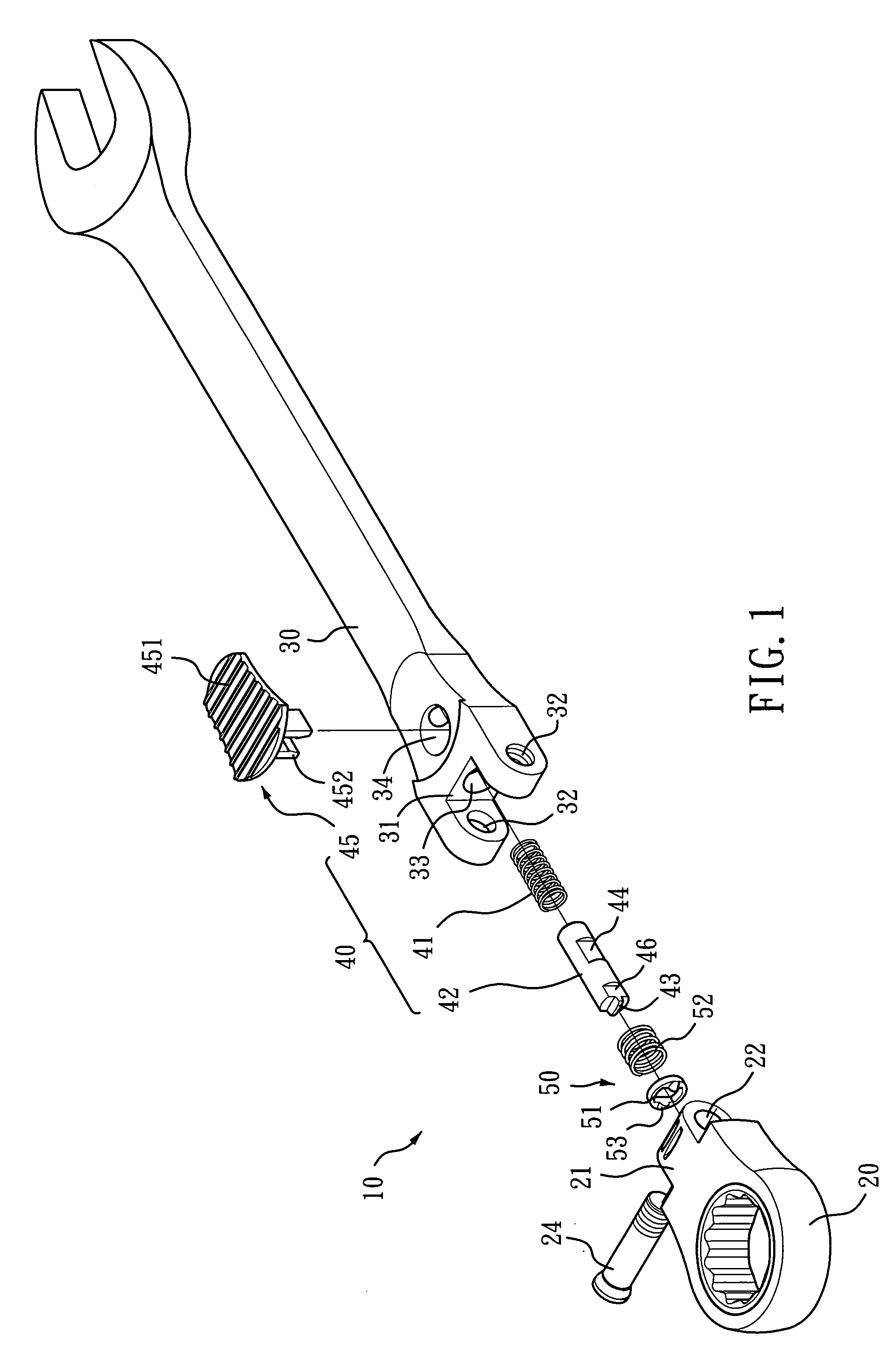
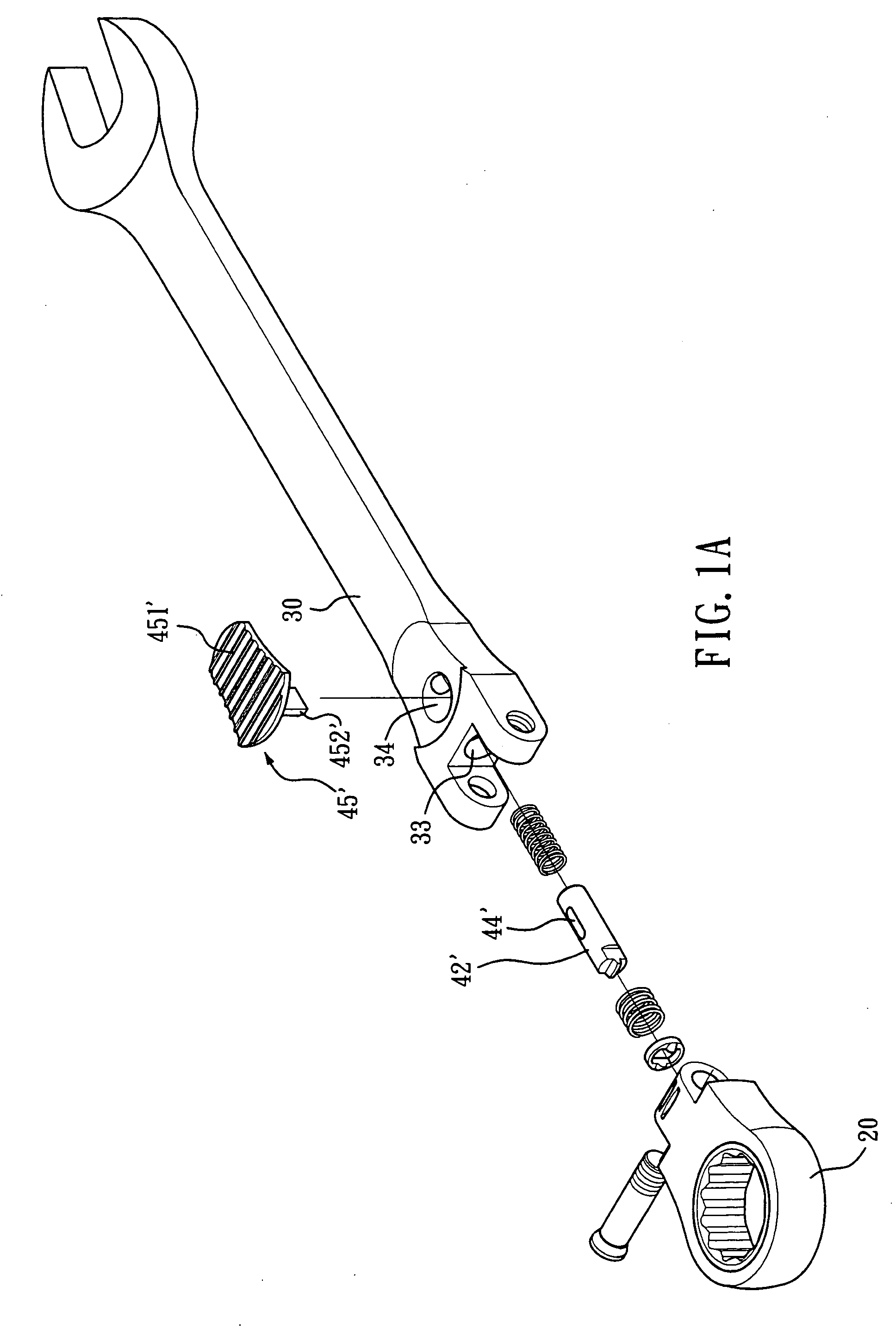
[0023]FIG. 1 illustrates an exploded view of a handle tool having an adjustable head with joint lock mechanism according to the present invention. A wrench 10 comprises a head 20, a handle 30 and a joint lock mechanism 40. A convex portion 21 is formed at a rear end of the head 20 and a through hole 22 is formed through the convex portion 21. A concave portion 31 is formed at a front end of the handle 30 and two through apertures 32 are formed at opposite sides thereof where one of the through apertures 32 is threaded to receive a screw 24 for pivotally coupling the head 20 to the handle 30. Regarding the configuration between the screw 24 and the two through holes 32, please refer to TW566274 for more details. A first aperture 33 is formed at the front end of the handle 30 and substantially extends along the length thereof, and a second aperture 34 is formed at one side of the handle 30 and perpendicularly intersects the first aperture 33.
[0024]A joint lock mechanism 40 comprises a...
PUM
 Abstract
Description
Claims
Application Information