Automatic tone correction apparatus, automatic tone correction method, and automatic tone correction program storage mediums

a tone correction and automatic technology, applied in the field of digital image processing apparatuses, can solve the problems of unfavorable graying of clothes, and inability to correct the back-lighted area of the image at all, so as to optimize the contrast and brightness of the forward-lighted image, suppress unintended correction, and achieve the effect of satisfying correction

Inactive Publication Date: 2006-11-28
PANASONIC CORP
View PDF13 Cites 48 Cited by
  • Summary
  • Abstract
  • Description
  • Claims
  • Application Information

AI Technical Summary

Benefits of technology

[0017]The present invention is made to solve the above-described problems and has for its object to provide an automatic tone correction apparatus, an automatic tone correction method, and an automatic tone correction program storage medium, that can realize satisfactory correction for a back-lighted image without collapsing a high-luminance part of the image, that can optimize the contrast and brightness of a forward-lighted image by the same processing as that for the back-lighted image, and that can suppress unintended correction.

Problems solved by technology

However, the tone correction method disclosed in Japanese Published Patent Application No. Hei.6-268866 has a drawback as follows.
Consequently, the back-lighted area of the image is not corrected at all.
Furthermore, as for a natural image such as a scenic shot, a natural image having a histogram the center of gravity of which is in the vicinity of the center tone is not always beautiful.
For example, when an image including a person who wears black clothes is corrected, the clothes unfavorably turn to gray.
In this method, however, accurate case branching is required, whereby the process is complicated and the volume of calculation is increased.
Moreover, different correction processes must be prepared for the respective cases, whereby the required storage capacity is increased, and the scale of the correction apparatus is increased, resulting in an increase in costs.
Furthermore, in the above-described methods, when a person exists in the center of the image and the area occupied by the person is small, since information of the person is hardly included in the histogram, an unintended correction is carried out, whereby a skin color region such as a face, which is visually conspicuous, occurs halation.

Method used


Image

  • Automatic tone correction apparatus, automatic tone correction method, and automatic tone correction program storage mediums
  • Automatic tone correction apparatus, automatic tone correction method, and automatic tone correction program storage mediums
  • Automatic tone correction apparatus, automatic tone correction method, and automatic tone correction program storage mediums

Examples


embodiment 1

[Embodiment 1]

[0123]Hereinafter, a description will be given of a first embodiment corresponding to inventions described in claims 1, 2, 3, 26, 27, 28, and 51 (further, claims 16˜25, 41˜50, 56˜63), with reference to the drawings.

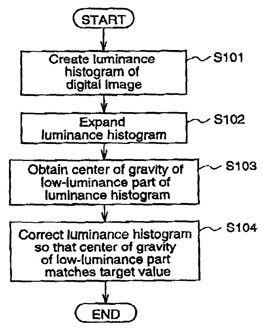
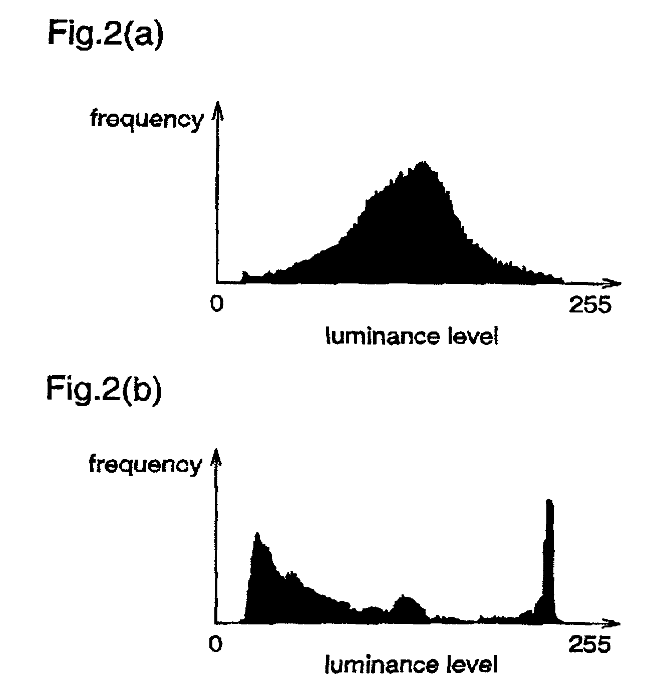
[0124]In this first embodiment, the whole luminance distribution of a luminance histogram is expanded over all tones to improve the contrast of an input image as a whole, and simultaneously, the luminance histogram is corrected so that the center of gravity of a low-luminance part of the histogram is shifted to a target value.

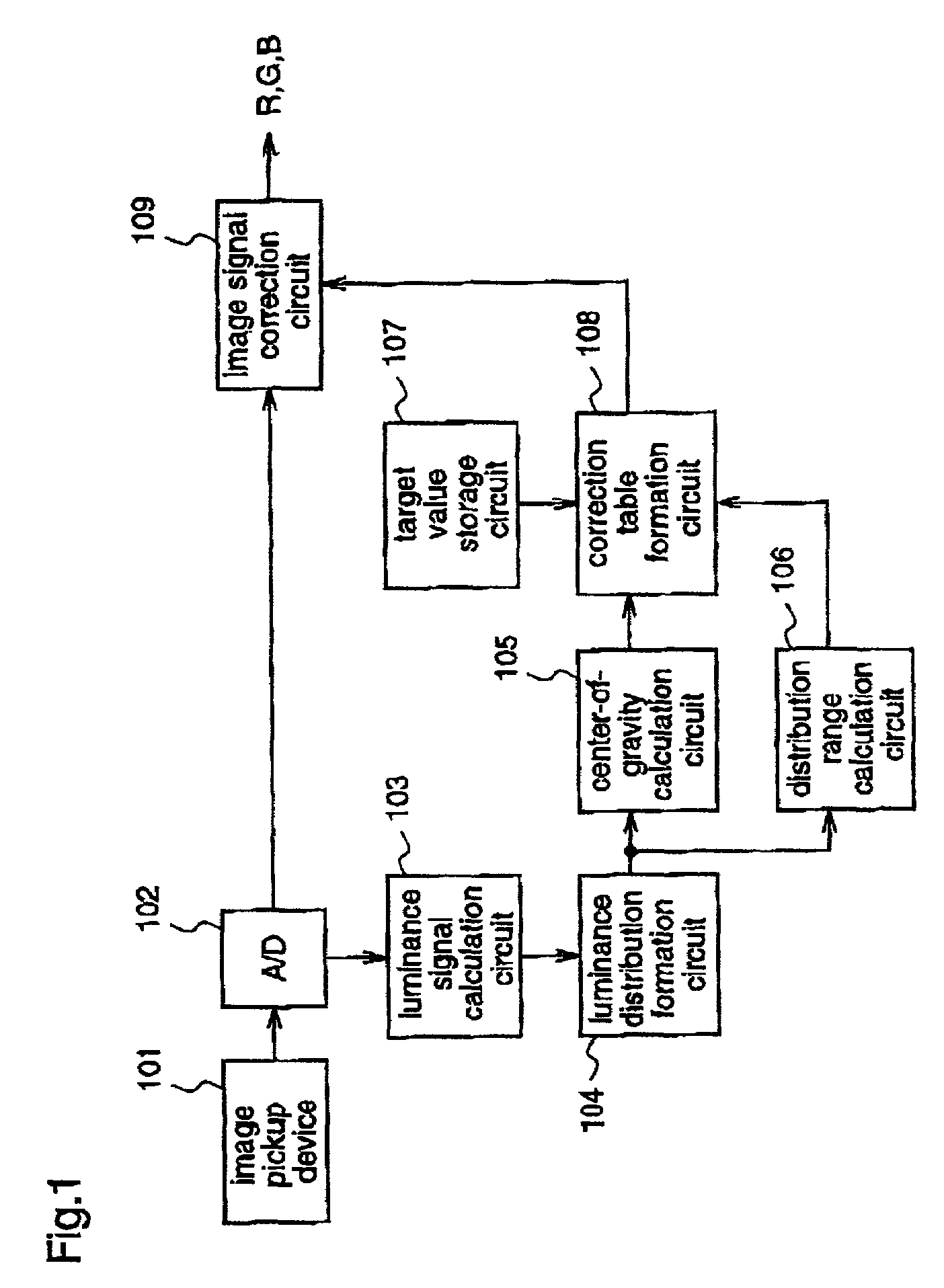
[0125]FIG. 1 is a block diagram illustrating an automatic tone correction apparatus according to the first embodiment. In FIG. 1, reference numeral 101 denotes an image pickup device for light-to-electricity converting a shot image; reference numeral 102 denotes an A / D converter to which an analog image signal is supplied from the image pickup device 101; reference. numeral 103 denotes a luminance signal calculation circuit to which a d...

embodiment 2

[Embodiment 2]

[0194]Hereinafter, a description will be given of a second embodiment of the present invention corresponding to claims 4, 5, 6, 29, 30, 31, and 52 (further, claims 16˜25, 41˜50, 56˜63), with reference to the drawings.

[0195]In this second embodiment, not a target value but a target luminance distribution is set to perform tone correction.

[0196]FIG. 17 is a block diagram illustrating an automatic tone correction apparatus according to the second embodiment. In FIG. 1, reference numeral 601 denotes an image pickup device for light-to-electricity converting a shot image; reference numeral 602 denotes an A / D converter to which an analog image signal is supplied from the image pickup device 601; reference numeral 603 denotes a luminance signal calculation circuit to which a digital image signal is supplied from the A / D converter 602; reference numeral 604 denotes a luminance distribution formation circuit (luminance histogram formation unit) to which a luminance signal is su...

embodiment 3

[Embodiment 3]

[0233]Hereinafter, a description will be given of a third embodiment of the present invention corresponding to claims 7, 32, and 35 (further, claims 8, 9, 16˜25, 33, 34, 41˜50, 56˜63), with reference to the drawings.

[0234]In this third embodiment, a boundary of a low-luminance part and a high-luminance part can be changed according to the center of gravity of a luminance histogram of an input image.

[0235]FIG. 24 is a block diagram illustrating an automatic tone correction apparatus according to the third embodiment.

[0236]In FIG. 24, reference numeral 1101 denotes an image pickup device for light-to-electricity converting a shot image; Preference numeral 1102 denotes an A / D converter to which an analog image signal is supplied from the image pickup device 1101; reference numeral 1103 denotes a luminance signal calculation circuit to which a digital image signal is supplied from the A / D converter 1102; reference numeral 1104 denotes a luminance distribution formation cir...


PUM


Abstract

An automatic tone correction apparatus comprises a luminance distribution formation circuit for forming a luminance histogram of an input image; a center-of-gravity calculation circuit for calculating the center of gravity of a low-luminance part of the luminance histogram; a distribution range calculation circuit for calculating a maximum value and a minimum value on an input luminance level axis; a target value storage circuit for holding a luminance correction target value; a correction table formation circuit for forming a correction table for expanding the luminance distribution and, simultaneously, correcting the luminance histogram so that the center of gravity matches the luminance correction target value; and an image signal correction circuit for performing tone correction on the basis of the correction table. Therefore, whether the input image is a forward-light image or a back-lighted image, the apparatus performs tone correction using the same processing.

Description

FIELD OF THE INVENTION[0001]The present invention relates to automatic tone correction apparatuses, automatic tone correction methods, and automatic tone correction program storage mediums. To be specific, the invention relates to an improved digital image processing apparatus that can correct an input image, more specifically, that can automatically correct tones of an input image.BACKGROUND OF THE INVENTION[0002]As a conventional technique for automatically correcting tones of an image, a method as follows has been well known. That is, a luminance value or a density value of each pixel of an input image is calculated, a histogram indicating the sum of pixels having the same value is formed, and all pixels are subjected to such a correction process that optimizes the shape of the histogram.[0003]For example, Japanese Published Patent Application No. Hei.6-268866 discloses a method for performing correction using a histogram as mentioned above. The method disclosed in this literatur...

Claims


Application Information

Patent Timeline
Patent Type & Authority Patents(United States)
IPC IPC(8): G06K9/00G06T5/40H04N1/407
CPCG06T5/009G06T5/40H04N1/4074
Inventor MARUOKA, KAZUTAKAFUJIMURA, FUMIO
Owner PANASONIC CORP
Why Eureka
Try Eureka