Imaging lens

a technology of imaging lens and image, which is applied in the field of imaging lens, can solve the problems of difficult to downsize the imaging lens while more satisfactorily correcting aberrations, and not being suitable for mounting in a small size, and achieve the effects of satisfactory aberration correction, small size and high resolution

Pending Publication Date: 2020-09-10
TOKYO VISIONARY OPTICS CO LTD
View PDF0 Cites 16 Cited by
  • Summary
  • Abstract
  • Description
  • Claims
  • Application Information

AI Technical Summary

Benefits of technology

[0008]According to the imaging lens of the invention, among the nine lenses, the arrangement of refractive power of the four lenses disposed on the object side is in the order of “positive-positive-negative-negative”, so that it is suitably achievable to downsize the imaging lens, while satisfactorily correcting the aberrations including a chromatic aberration. In the imaging lens of the invention, among the lenses, the first lens having positive refractive power is disposed to be the closest to the object side, and the second lens similarly having positive refractive power is disposed on an image plane side of the first lens. According to the lens configuration of the invention, where positive refractive power is shared between the two lenses, it is achievable to restrain increase of refractive power of the first lens accompanied with downsizing of the imaging lens. Therefore, it is achievable to suitably downsize the imaging lens. In addition, in the first lens, a ratio of uneven lens thickness, i.e., a ratio of thicknesses between the thinnest part and the thickest part of the lens, can be kept small. Therefore, it is achievable to suitably restrain within a satisfactory range so-called “manufacturing error sensitivity”, i.e., sensitivity to deterioration of image-forming performance in decentering, tilting, etc., which occurs in manufacturing of the imaging lens. Moreover, since the ratio of unevenness of the lens thickness is small, flowability of a lens material upon molding the lens can be improved, so that it is also achievable to reduce the manufacturing cost of the first lens.
[0087]According to the imaging lens of the invention, it is achievable to provide an imaging lens having a small size, which is especially suitable for mounting in a small-sized camera, while having high resolution with satisfactory correction of aberrations.

Problems solved by technology

In case of the conventional imaging lens of Patent Reference, a total track length is long relative to a focal length of the whole lens system, so that it is not suitable to mount in a small-sized camera, such as the one to be built in a smartphone.
In case of the conventional imaging lens having the above-described configuration, it is difficult to downsize the imaging lens while more satisfactorily correcting the aberrations.

Method used


Image

  • Imaging lens
  • Imaging lens
  • Imaging lens

Examples


Embodiment Construction

[0118]Hereunder, referring to the accompanying drawings, an embodiment of the present invention will be fully described.

[0119]Hereunder, referring to the accompanying drawings, an embodiment of the present invention will be fully described.

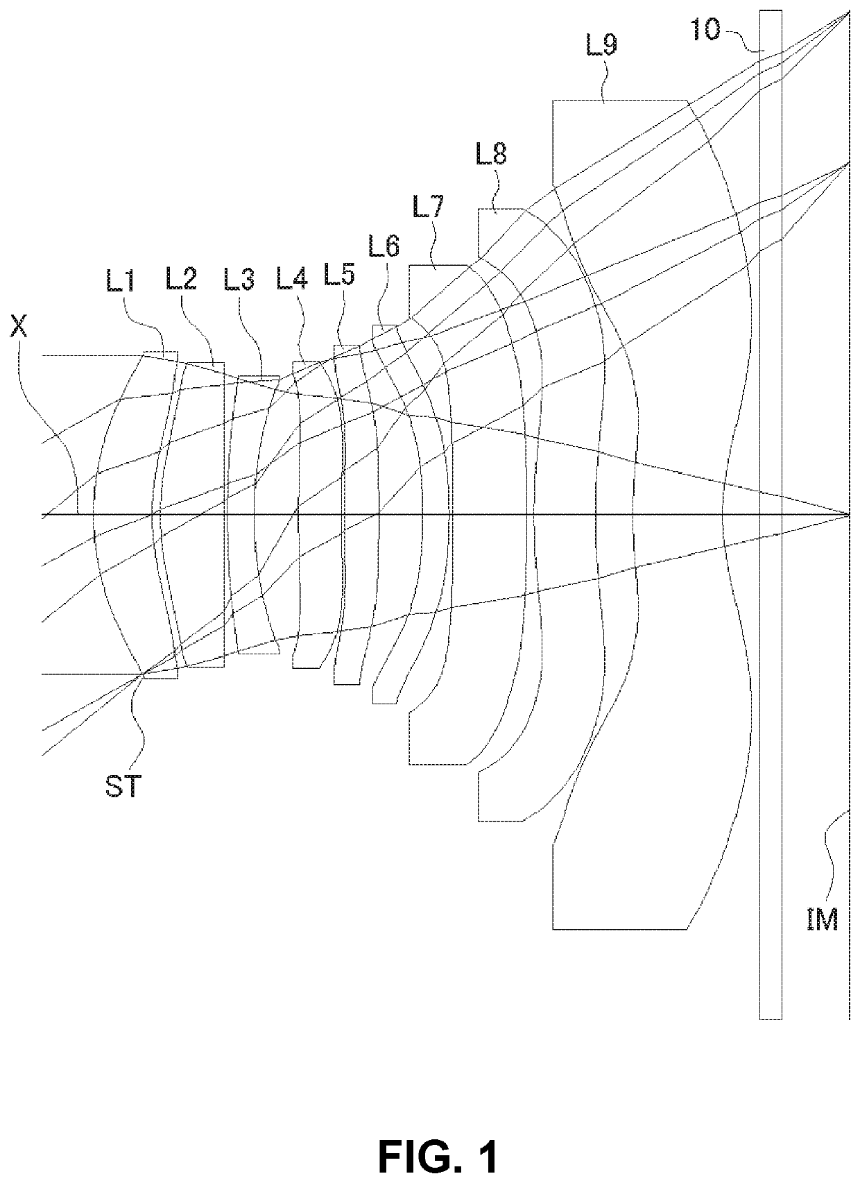
[0120]FIGS. 1, 4, 7, 10, 13, 16, 19, 22, 25 and 28 are schematic sectional views of the imaging lenses in Numerical Data Examples 1 to 10 according to the embodiment, respectively. Since the imaging lenses in those Numerical Data Examples have the same basic configuration, the lens configuration of the embodiment will be described with reference to the sectional view of Numerical Data Example 1.

[0121]As shown in FIG. 1, the imaging lens of the embodiment includes a first lens L1 having positive refractive power; a second lens L2 having positive refractive power; a third lens L3 having negative refractive power; a fourth lens L4 having negative refractive power; a fifth lens L5; a sixth lens L6; a seventh lens L7; an eighth lens L8; and a ninth len...


PUM


Abstract

An imaging lens includes a first lens having positive refractive power; a second lens having positive refractive power; a third lens having negative refractive power; a fourth lens having negative refractive power; a fifth lens; a sixth lens; a seventh lens; an eighth lens; and a ninth lens having negative refractive power, arranged in this order from an object side to an image plane side. The ninth lens is formed in a shape so that a surface thereof on the image plane side has an aspherical shape having an inflection point.

Description

BACKGROUND OF THE INVENTION AND RELATED ART STATEMENT[0001]The present invention relates to an imaging lens for forming an image of an object on an imaging element such as a CCD sensor and a CMOS sensor. In particular, the present invention relates to an imaging lens suitable for mounting in a relatively small camera such as a camera to be built in a portable device, e.g., a cellular phone and a portable information terminal, a digital still camera, a security camera, an onboard camera, and a network camera.[0002]In case of a lens configuration comprised of nine lenses, since the number of lenses that composes the imaging lens is many, it has higher flexibility in designing and can satisfactorily correct aberrations. For example, as the conventional imaging lens having a nine-lens configuration, an imaging lens described in Patent Reference has been known.[0003]Patent Reference: Japanese Patent Application Publication No. 2018-156011[0004]According to the conventional imaging lens o...

Claims


Application Information

Patent Timeline
Patent Type & Authority Applications(United States)
IPC IPC(8): G02B9/64G02B13/00G02B27/00H04N5/225
CPCG02B9/64G02B13/0045H04N5/2254G02B27/0025G02B13/06G02B13/18G03B30/00H04N23/55
Inventor HIRANO, HITOSHI
Owner TOKYO VISIONARY OPTICS CO LTD
Why Eureka
Try Eureka