

Image pickup lens
a technology of image pickup and lens, which is applied in the field of image pickup lenses, can solve the problems of insufficient brightness, insufficient response, and severe demand for downsizing and thinning of the imaging devices built in,
- Summary
- Abstract
- Description
- Claims
- Application Information
AI Technical Summary
Benefits of technology
Problems solved by technology
Method used
Image

Examples
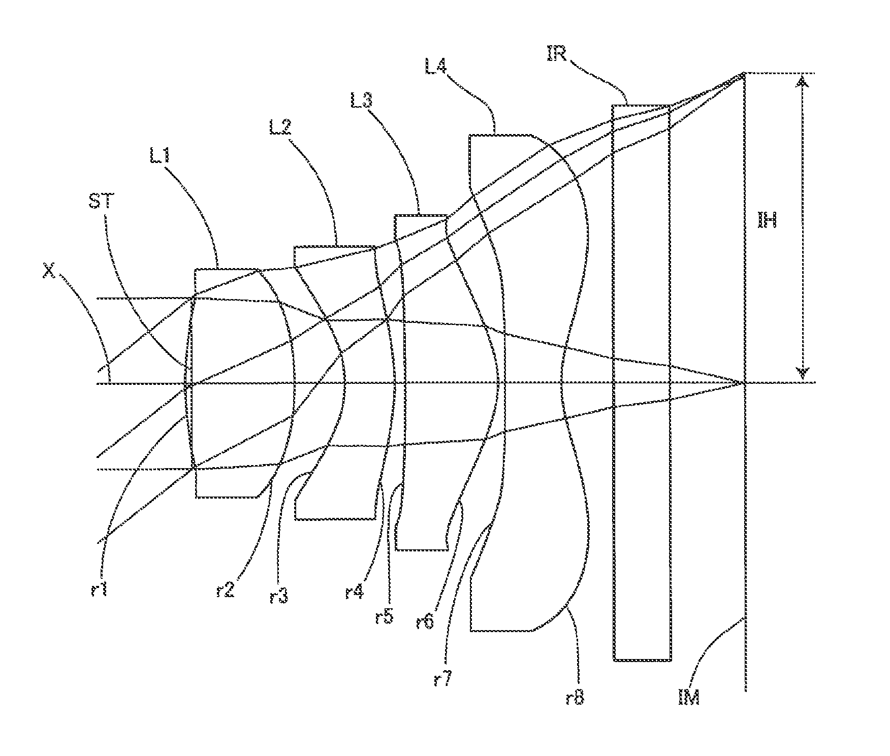
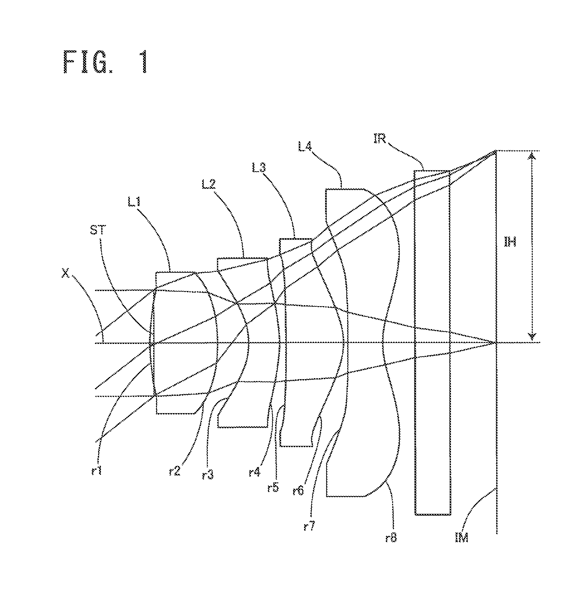
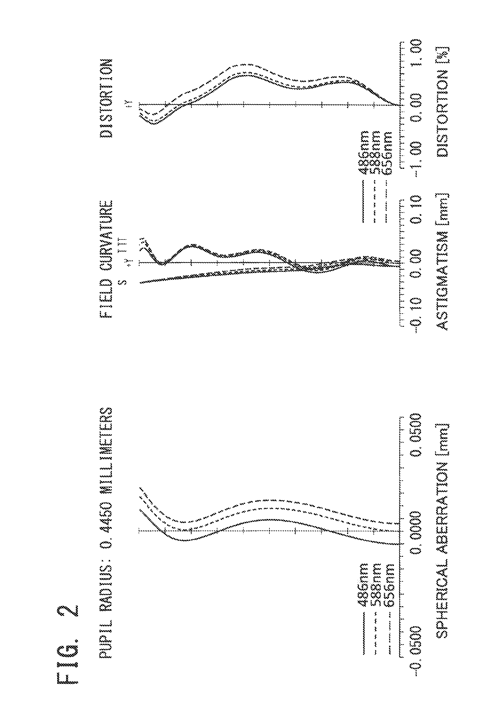
embodiment 1
[0068]Basic lens data will be shown in Table 1 below.
TABLE 1Embodiment 1Unit mmf = 2.143Fno = 2.408ω = 36.91°Surface dataSurfaceRefractiveAbbe No.Surface No. iCurvature radius rdistance dindex Ndνd(Object surface)InfinityInfinityStopInfinity−0.0341*1.46850.5861.53462256.16032*−1.48720.2683*−0.56550.271.63548923.91144*−1.24110.0545*−8.71350.49881.53462256.16036*−0.51540.03817*−106.54540.31.53462256.16038*0.56870.289 Infinity0.31.51479854.198310 Infinity0.4244Image PlaneInfinitySingle lens dataLensStart surfaceFocal length111.478923−1.9222350.999247−1.0528Aspheric dataFirst surfaceSecond surfaceThird surfaceFourth surfacek0−26.3−0.311−1.63A4−2.179E−01−1.304E+006.668E−018.918E−03A6−7.746E−011.496E+00−2.500E+002.435E+00A82.453E+00−1.059E+003.525E+01−1.255E+01A10−1.367E+01−3.647E+00−1.084E+024.448E+01A120.000E+001.447E+001.227E+02−7.945E+01A140.000E+000.000E+000.000E+005.302E+01A160.000E+000.000E+000.000E+000.000E+00Fifth surfaceSixth surfaceSeventh surfaceEighth surfacek0−4.80−6.7A4−1.2...
embodiment 2
[0072]Basic lens data will be shown in Table 2 below.
TABLE 2Embodiment 2Unit mmf = 2.113Fno = 2.414ω = 37.31°Surface dataSurfaceRefractiveAbbe No.Surface No. iCurvature radius rdistance dindex Ndνd(Object surface)InfinityInfinityStopInfinity−0.031*1.530.5831.53462256.16032*−1.40530.2693*−0.55420.271.63548923.91144*−1.17670.04835*−6.30970.51931.53462256.16036*−0.47660.027*−99.00840.31.53462256.16038*0.5244920.289 Infinity0.31.51479854.198310 Infinity0.4272Image planeInfinitySingle lens dataLensStart surfaceFocal length111.467523−1.9697350.932347−0.9717Aspheric dataFirst surfaceSecond surfaceThird surfaceFourth surfacek0−21.8−0.34−2.2A4−2.260E−01−1.305E+007.278E−013.080E−02A6−8.538E−011.510E+00−2.477E+002.405E+00A82.592E+00−1.029E+003.497E+01−1.258E+01A10−1.406E+01−3.746E+00−1.082E+024.436E+01A120.000E+001.447E+001.227E+02−7.945E+01A140.000E+000.000E+000.000E+005.302E+01A160.000E+000.000E+000.000E+000.000E+00Fifth surfaceSixth surfaceSeventh surfaceEighth surfacek0−4.580−6.9A4−1.316E−...
embodiment 3
[0076]Basic lens data will be shown in Table 3 below.
TABLE 3Embodiment 3Unit mmf = 2.158Fno = 2.407ω = 36.73°Surface dataSurfaceRefractiveAbbe No.Surface No. iCurvature radius rdistance dindex Ndνd(Object surface)InfinityInfinityStopInfinity−0.0451*1.26760.5871.53462256.16032*−1.81290.23243*−0.57890.271.63548923.91144*−1.08630.08145*−2.56750.46381.53462256.16036*−0.47050.027*−1000.31.53462256.16038*0.54240.289 Infinity0.31.51479854.198310 Infinity0.4747Image planeInfinitySingle lens dataLensStart surfaceFocal length111.490023−2.4434350.997147−1.0047Aspheric dataFirst surfaceSecond surfaceThird surfaceFourth surfacek0−41−0.3501−2.9019A4−2.135E−01−1.232E+002.837E−014.750E−02A6−1.939E−013.398E−01−3.272E+002.188E+00A85.075E−011.356E+003.821E+01−1.284E+01A10−1.176E+01−5.494E+00−1.100E+024.564E+01A120.000E+003.441E+001.208E+02−7.967E+01A140.000E+000.000E+000.000E+005.049E+01A160.000E+000.000E+000.000E+000.000E+00Fifth surfaceSixth surfaceSeventh surfaceEighth surfacek12.4393−4.46320−7.664...
PUM
 Abstract
Description
Claims
Application Information