Zoom lens and imaging apparatus

a technology of zoom lens and imaging apparatus, applied in the direction of optics, instruments, optical elements, etc., can solve the problems of unreachable, large amount of back focus not secured, excessively large lens system, etc., and achieve the effect of high-quality video imag

Active Publication Date: 2015-05-14
FUJIFILM CORP
View PDF0 Cites 15 Cited by
  • Summary
  • Abstract
  • Description
  • Claims
  • Application Information

AI Technical Summary

Benefits of technology

[0008]However, it cannot be said that the lenses disclosed in Patent Documents 1 and 2 are those which are sufficiently compact, because they have long total lengths, partly because these lenses secure a large amount of back focus.
[0011]The present invention has been developed in view of the above circumstances. It is an object of the present invention to provide a compact zoom lens having a short total length in which a wider angle of view is achieved and various aberrations are satisfactorily corrected, and an imaging apparatus including lens.
[0013]the first lens group through the fourth lens group move along the optical axis while changing magnification from the wide angle end to the telephoto end so as to change the distances among one another such that the distance between the first lens group and the second lens group is reduced and the distance between the second lens group and the third lens group is increased;
[0035]the first lens group through the fourth lens group move along the optical axis while changing magnification from the wide angle end to the telephoto end so as to change the distances among one another such that the distance between the first lens group and the second lens group is reduced and the distance between the second lens group and the third lens group is increased;
[0038]As the imaging apparatus of the present invention include the zoom lens of the present invention, miniaturization can be achieved and a high quality video image can be obtained.

Problems solved by technology

However, it cannot be said that the lenses disclosed in Patent Documents 1 and 2 are those which are sufficiently compact, because they have long total lengths, partly because these lenses secure a large amount of back focus.
Further, the lens disclosed in Patent Document 3 has a configuration in which a large amount of back focus is not secured.
This causes a problem that the lens system will be made excessively large.

Method used


Image

  • Zoom lens and imaging apparatus
  • Zoom lens and imaging apparatus
  • Zoom lens and imaging apparatus

Examples


Embodiment Construction

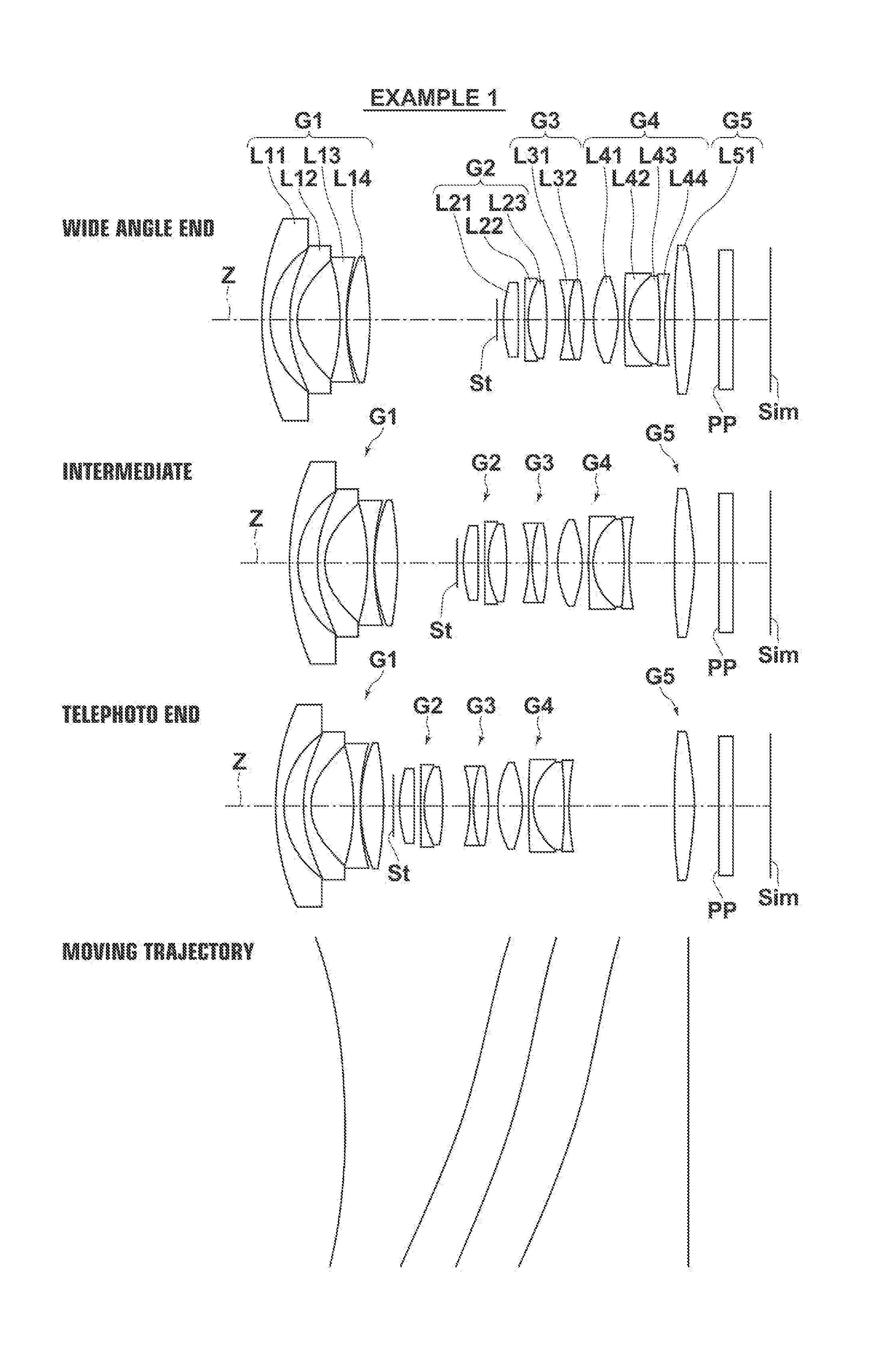
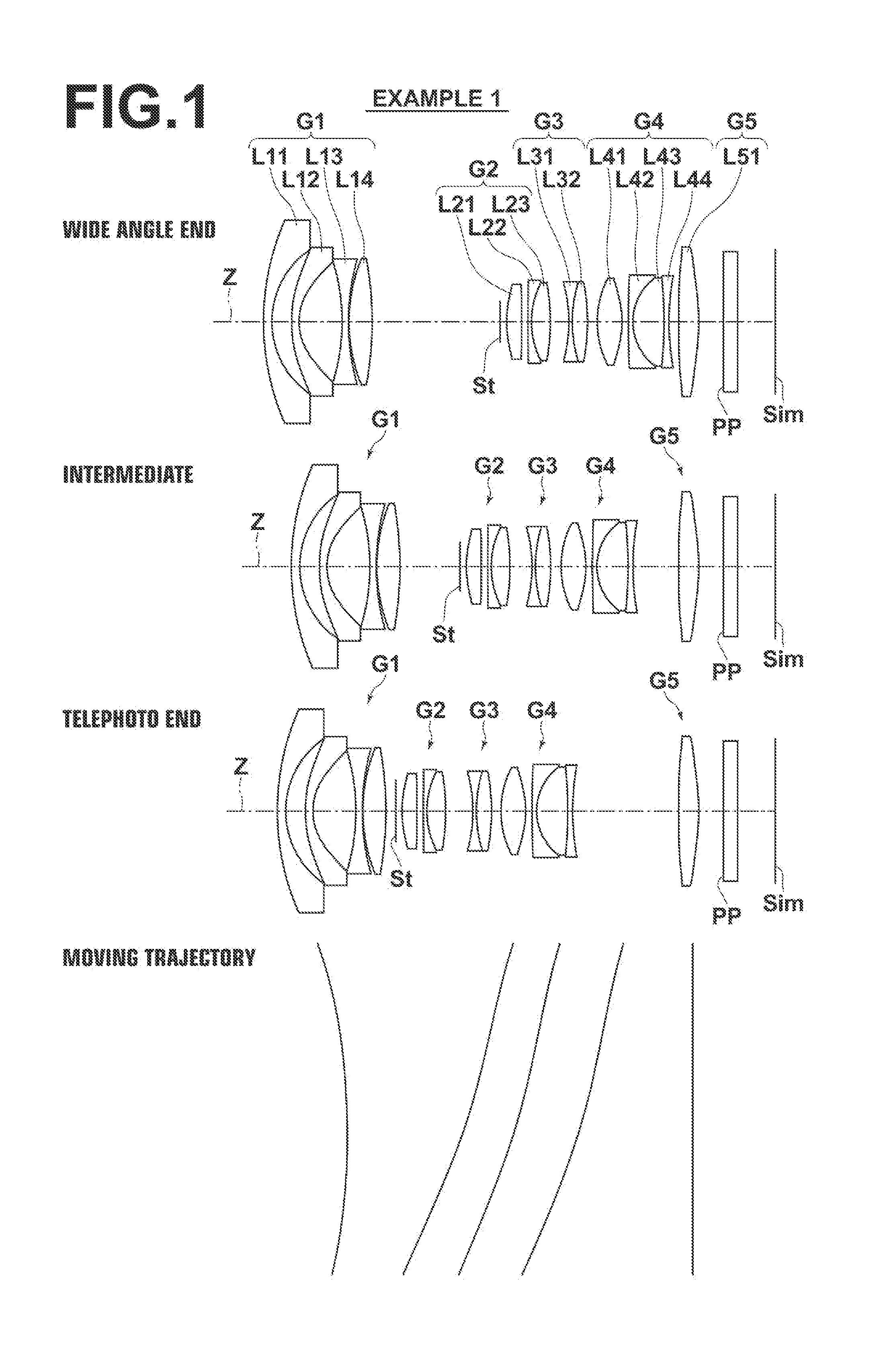
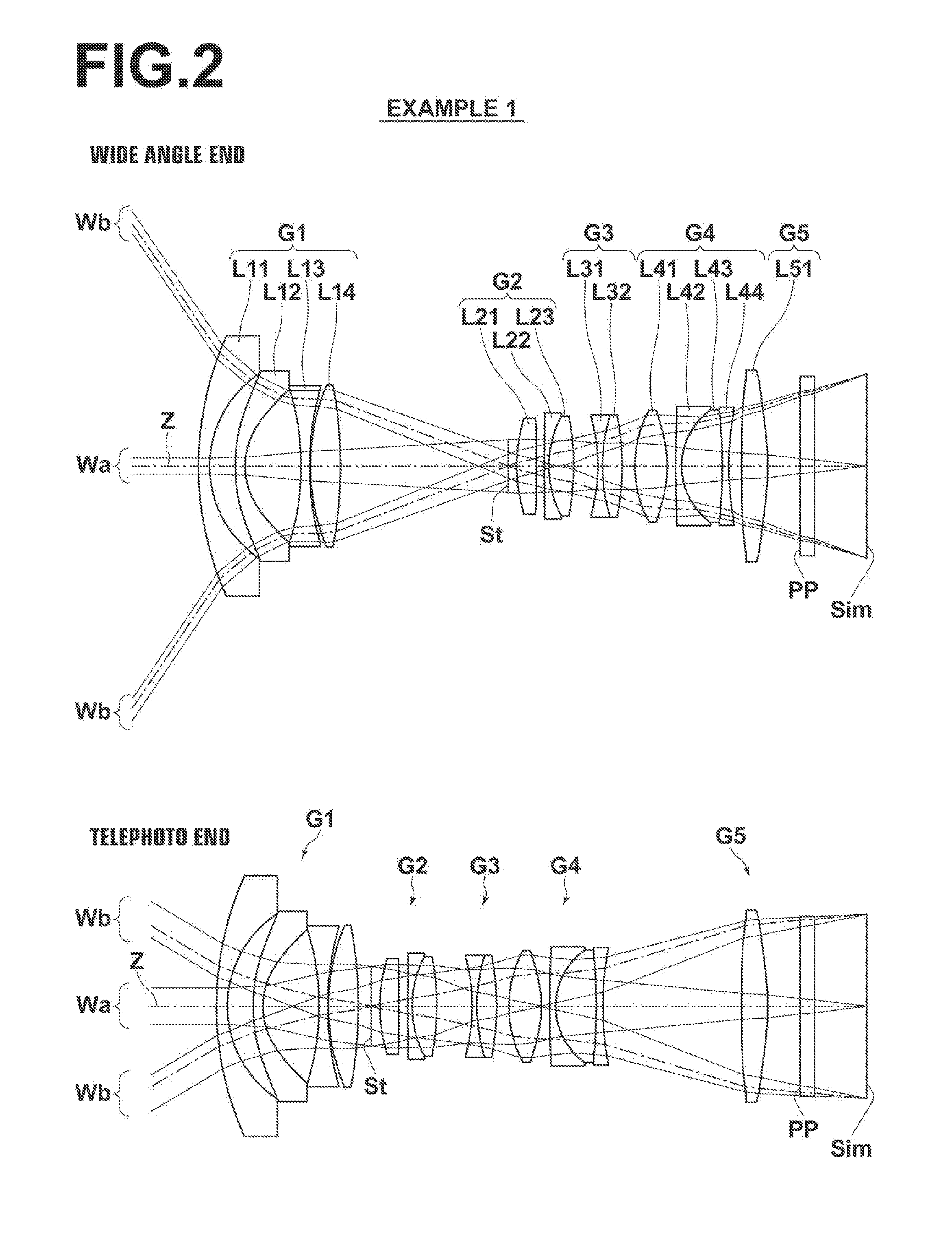
[0052]Hereinafter, embodiments of the present invention will be described in detail with reference to the accompanying drawings. FIG. 1 is a collection of cross-sectional views of a zoom lens according to one embodiment of the present invention, illustrating the lens configuration thereof. FIG. 2 is a collection of views illustrating optical paths of the zoom lens described above. The example of a configuration shown in each of FIGS. 1 and 2 is the same as the configuration of the zoom lens of Example 1 to be described later. In FIGS. 1 and 2, the left side is the object side, and the right side is the image side. In addition, FIG. 2 also shows axial rays wa and rays wb having the maximum angle of view.

[0053]As shown in FIGS. 1 and 2, this zoom lens consists of a first lens group G1 having a negative refractive power, a stop St, a second lens group G2 having a positive refractive power, a third lens group G3 having a negative refractive power, a fourth lens croup G4 having a positiv...


PUM


Abstract

A zoom lens substantially consists of a negative first lens group, a stop, a positive second lens group, a negative third lens group, a positive fourth lens group, and a positive fifth lens group in this order from the object side; whereinthe first lens group through the fourth lens group move along the optical axis while changing magnification such that the distance between the first lens group and the second lens group is reduced and the distance between the second lens group and the third lens group is increased;the fifth lens group is fixed with respect to an image surface while changing magnification; andthe first lens group substantially consists of an eleventh lens, a twelfth lens, a thirteenth lens, and a fourteenth lens in this order from the object side.

Description

CROSS-REFERENCE TO RELATED APPLICATIONS[0001]The present application claims priority under 35 U.S.C. §119 to Japanese Patent Application No. 2013-234860, filed on Nov. 13, 2013. The above application is hereby expressly incorporated by reference, in its entirety, into the present application.BACKGROUND OF THE INVENTION[0002]1. Technical Field[0003]The present invention relates to a zoom lens suited for electronic cameras such as a digital camera, a video camera, a broadcasting camera, a movie camera, a surveillance camera, and the like, and to an imaging apparatus including the zoom lens.[0004]2. Description of the Related Art[0005]Conventionally, zoom type lenses in which a first lens group having a negative refractive power and a second lens group having a positive refractive power are arranged in front in this order from the object side are proposed as simple configurations of zoom lenses.[0006]Further, some of those zoom type lenses, which achieve a wider angle of view as imagin...

Claims


Application Information

Patent Timeline
Patent Type & Authority Applications(United States)
IPC IPC(8): G02B15/177G02B13/04
CPCG02B13/04G02B15/177G02B15/145527G02B15/16
Inventor NODA, TAIGA
Owner FUJIFILM CORP
Why Eureka
Try Eureka