Broadband coupler technique for electrical connection to power lines

a broadband coupler and power line technology, applied in the direction of coupling device connection, modulated carrier system, electric signalling details, etc., can solve the problems of power line communication system limited to relatively low data rate, not originally designed for data transmission, and the inability to achieve high data rate of bpl system using carrier frequency below 525 khz

Active Publication Date: 2006-12-05
AMERICAN TELEPHONE & TELEGRAPH CO
View PDF13 Cites 238 Cited by
  • Summary
  • Abstract
  • Description
  • Claims
  • Application Information

AI Technical Summary

Benefits of technology

[0006]The invention provides a power line broadband communication system having broadband coupler devices capable of direct electrical connection to an energized power line without creating unreasonable safety risks.
[0010]In one embodiment the coupler device carries signals to and from transceivers associated with customer premises. Such transceivers may have wired connections via transformer bypass router lines to and from customer premises. Other exemplary transceivers may be wireless transceivers that eliminate any need for a transformer bypass line.
[0015]In some embodiments, the conductive portion of the coupler is connected to a broadband signal line through a capacitor. The technique of the present invention as implemented in certain embodiments helps to make capacitive coupling cost competitive with inductive coupling, thereby taking advantage of the fact that capacitive coupling is more efficient for broadband signals. The impedance of a capacitive coupler (i.e., its ability to obstruct the flow of signal energy) decrease with signal frequency. With an inductive coupler, the impedance increase with frequency. Thus the capacitive coupler is better suited to cases where we want to use high-frequency broadband signals.
[0016]Because a capacitive coupler device requires direct electric conductive contact with an energized power line, the coupler installation device and method of the present invention greatly facilitate the capability of enjoying the benefits of capacitive coupling for broadband power line communication systems as compared with inductive coupling.

Problems solved by technology

Initially, power line communication systems were limited to relatively low data rates, typically less than 500 kbs.
While existing power line systems are capable of transmitting data at the rates described above, they were not initially designed for data transmission.
However, the high data rates of BPL systems cannot be achieved using carrier frequencies below 525 kHz.
Providing an electrical coupling to medium voltage (MV) and low voltage (LV) power lines as part of a broadband communication system is a dangerous task.

Method used


Image

  • Broadband coupler technique for electrical connection to power lines
  • Broadband coupler technique for electrical connection to power lines
  • Broadband coupler technique for electrical connection to power lines

Examples


Embodiment Construction

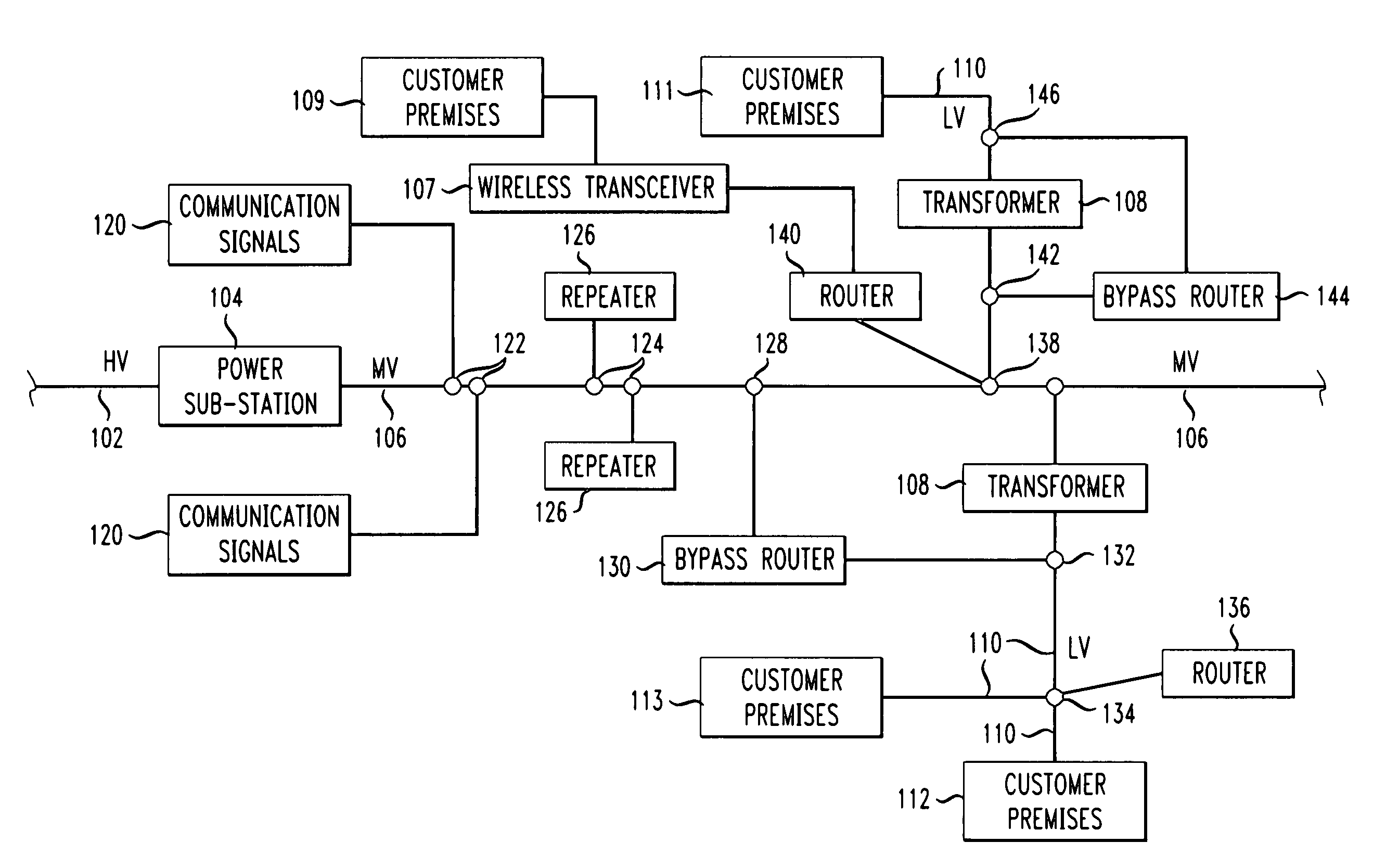
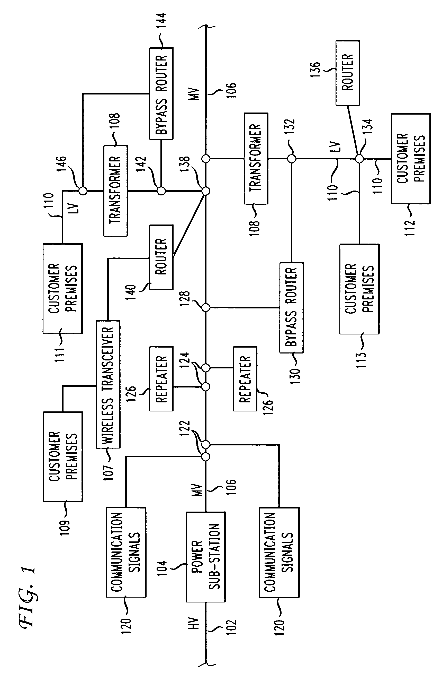
[0026]A typical power line communication system for implementing features of the invention is shown in FIG. 1. A high voltage (HV) power line 102 transmits power through sub-station 104 to a medium voltage (MV) power line 106 that eventually may connect through a transformer 108 to low voltage (LV) lines 110 that provide alternating electrical power to customer premises 111, 112, 113. A wireless connection through transceiver 107 may provide an alternative connection to customer premises 109.

[0027]A head end data network provides communication signals 120 via a fiber optic cable or other suitable transmission links to the end user customer premises 111, 112, 113 using power line cables as the transmission medium. Techniques for converting data signals to the electrical domain for transmission via the power lines are well known. A transmitter contains a modulator which modulates the incoming data onto a carrier signal using well known RF modulation techniques. As described above, typ...


PUM


Abstract

Disclosed is a power line broadband communication system having broadband coupler devices capable of direct electrical connection to an energized power line. The coupler includes a conductive portion movable by an adjustable member from a non-conducting retracted position spaced apart from the power transmission line to a forward conducting position in electrical contact with the power line. An insulated arm supports the coupler on the power line. A base on the coupler is engageable with a remotely activated tool in order to accomplish the electrical connection in a safe and secure manner. Broadband data signals are sent to and from customer premises along the shared energized power lines. New coupler connections to the energized power lines allow the additional broadband customers and / or repeaters to join the communication system. Also couplers may provide connections to control electronics, routers, wireless transceivers, and may allow the broadband signals to bypass transformers on the power lines. The invention helps to minimize risk by allowing an installer to be remotely spaced from the energized power line while making the electrical coupling contact with the energized power line.

Description

BACKGROUND OF THE INVENTION[0001]This application relates generally to data transmission, and more particularly to data transmission over power lines.[0002]The use of power lines to transmit data is known. Initially, power line communication systems were limited to relatively low data rates, typically less than 500 kbs. These low data rates are generally useful for applications such as remote control of various switches connected to the power line system. More recently, developments have been made in the area of broadband power line communication systems, also known as power line telecommunications (PLT) systems or broadband power line (BPL) systems. These systems are capable of transmitting data at significantly higher data rates than previous systems. For example, BPL systems can transmit data at rates of 4–20 Mbps.[0003]While existing power line systems are capable of transmitting data at the rates described above, they were not initially designed for data transmission. Instead, ...

Claims


Application Information

Patent Timeline
Patent Type & Authority Patents(United States)
IPC IPC(8): H04M11/04
CPCH04B3/542H04B3/56H04B2203/5441H04B2203/5479H04B2203/5483H04B2203/5491
Inventor GERSZBERG, IRWINHENRY, PAUL SHALA
Owner AMERICAN TELEPHONE & TELEGRAPH CO
Why Eureka
Try Eureka