Leakage inductance saturation compensation for a slip control technique of a motor drive

a technology of leakage inductance saturation and motor drive, which is applied in the direction of motor/generator/converter stopper, dynamo-electric converter control, dynamo-electric gear control, etc., can solve the problems of leakage inductance varies and the difficulty of accurate torque control over a wide torque rang

Active Publication Date: 2007-03-06
ROCKWELL AUTOMATION TECH
View PDF34 Cites 26 Cited by
  • Summary
  • Abstract
  • Description
  • Claims
  • Application Information

AI Technical Summary

Benefits of technology

[0014]Therefore unlike previous motor drives, the present method adjusts the value of the leakage inductance which is used in deriving the voltage commands that control the motor.

Problems solved by technology

However, the leakage inductance varies due to saturation effects as the motor load increases.
Therefore, accurate torque control becomes difficult over a wide torque range when a constant value for the leakage inductance is used for slip control.

Method used


Image

  • Leakage inductance saturation compensation for a slip control technique of a motor drive
  • Leakage inductance saturation compensation for a slip control technique of a motor drive
  • Leakage inductance saturation compensation for a slip control technique of a motor drive

Examples


Embodiment Construction

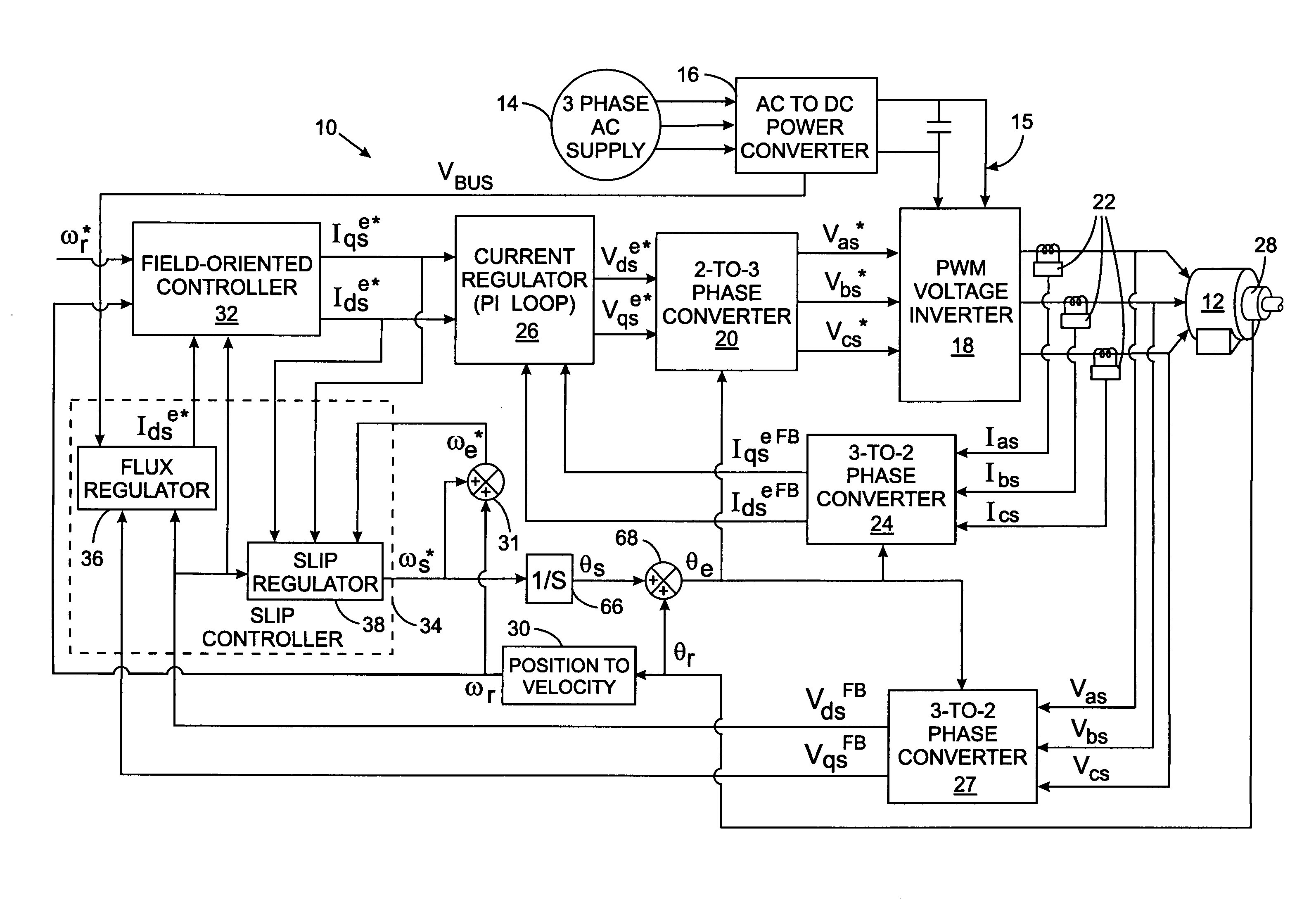
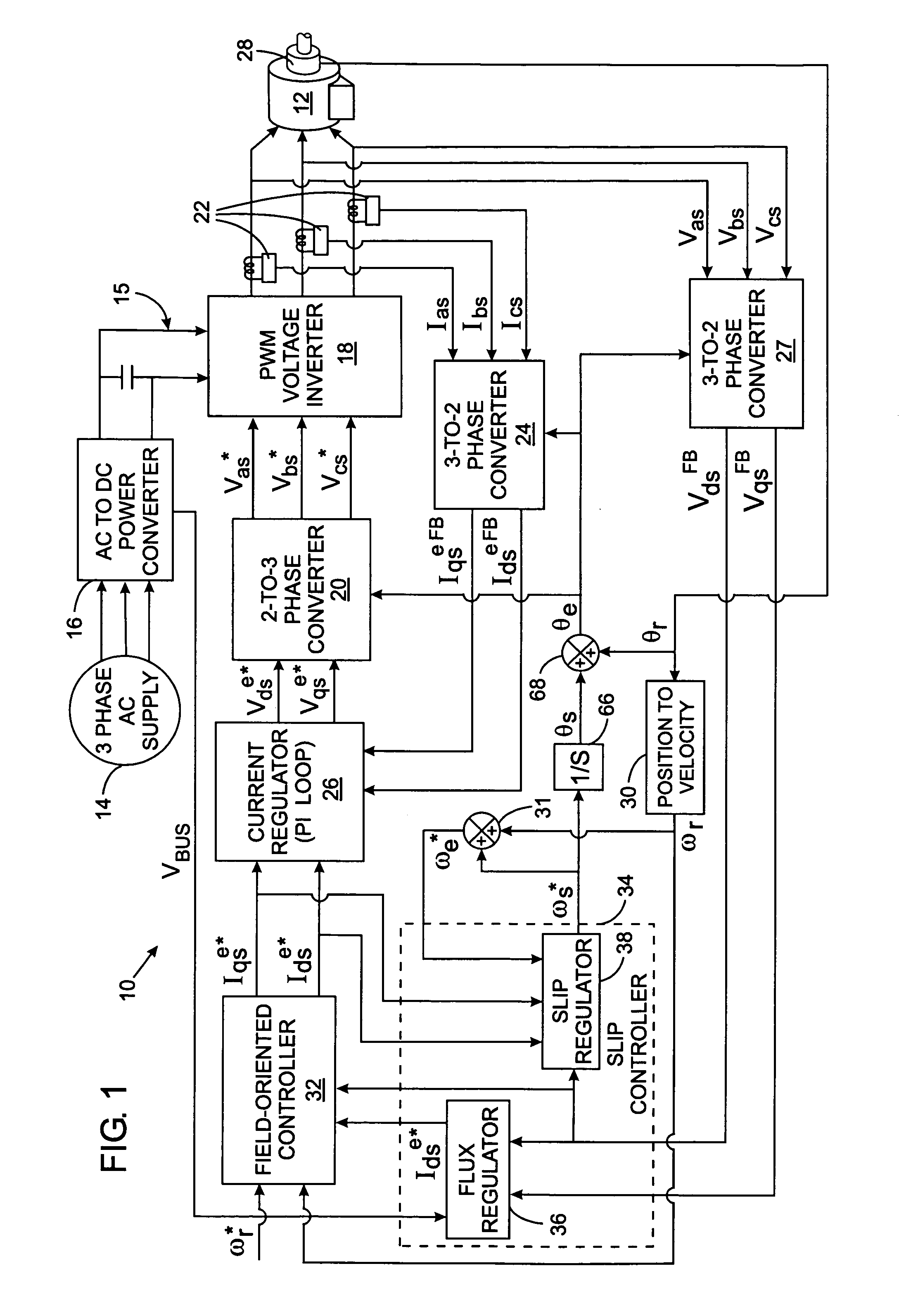
[0018]FIG. 1 illustrates a current-regulated, pulse width modulation motor controller, also called a “motor drive”, 10 for an alternating current (AC) induction motor 12. The motor drive 10 includes a power section that receives electricity from a three-phase power supply 14. The three phases are connected to an alternating current (AC) to direct current (DC) power converter 16 that rectifies the alternating currents from the power supply 14 to produce a DC voltage on a bus 15. The DC bus 15 is connected to a pulse width modulation (PWM) voltage inverter 18, which completes the power section of the motor drive 10. The AC-DC power converter 16 also produces a feedback control signal VBUS that indicates the voltage level on the DC bus 15.

[0019]The conventional PWM voltage inverter 18 includes a group of solid state switching devices which are turned on and off by control signals to convert the input DC voltage to pulses of constant magnitude on three output lines connected to the moto...


PUM


Abstract

An electronic drive for vector control of an induction motor controls slip and operating frequency in response to changes in stator voltage. The drive includes a torque control loop, a flux control loop and a frequency control loop. The control is based on a commanded stator current that is resolved into a torque-producing, or q-axis, current component and a flux-producing, or d-axis, current component that are in quadrature. The frequency control loop includes slip control in which a slip frequency command is produces based on a value for the leakage inductance of the motor. The leakage inductance value dynamically varies as a function of the q-axis current reference command.

Description

CROSS-REFERENCE TO RELATED APPLICATIONS[0001]Not ApplicableSTATEMENT REGARDING FEDERALLY SPONSORED RESEARCH OR DEVELOPMENT[0002]Not ApplicableBACKGROUND OF THE INVENTION[0003]1. Field of the Invention[0004]The present invention relates to high performance, electronic motor drives for variable speed or torque control of AC induction motors, and more particularly, to such motor drives which use vector control techniques and velocity feedback.[0005]2. Description of the Related Art[0006]Motor drives are commonly employed to control the application of electricity to a three-phase AC induction motor. Such motor drives include an inverter which switches DC voltage to output lines in a pulse width modulated (PWM) manner to control the frequency and amount of voltage applied to the motor and thus the motor velocity.[0007]Vector control or field-oriented control is one technique used in a motor drive to control the speed and torque of the motor. With this technique, stator current is resolve...

Claims


Application Information

Patent Timeline
Patent Type & Authority Patents(United States)
IPC IPC(8): H02P21/08H02P23/08
CPCH02P21/085H02P21/09
Inventor MATSUO, TAKAYOSHITHUNES, JERRY
Owner ROCKWELL AUTOMATION TECH
Why Eureka
Try Eureka