Failsafe control circuit for electrical appliances

a control circuit and electrical appliance technology, applied in logic circuits, automatic controllers, programme control, etc., can solve the problems of power relay contacts being closed, transistor short circuit, power relay overvoltage, etc., to achieve high simplicity and reliability, and low cost

Inactive Publication Date: 2007-03-06
EIKA S COOP LTDA
View PDF17 Cites 1 Cited by
  • Summary
  • Abstract
  • Description
  • Claims
  • Application Information

AI Technical Summary

Benefits of technology

[0007]The main object of the invention is to provide a failsafe control circuit for electrical appliances. A second object of the invention is to provide a failsafe circuit of high simplicity and reliability and low cost.
[0010]The main advantage of the control circuit of the invention is that it is safe in the event of failure of any of its components, including the failure of the logic control means and the failure of the operation switching means or the security switching means. This implies that, if any of said components fail, there is no risk that the electrical load is energized uninterruptedly, thus providing safety to the users.
[0011]Furthermore, another important advantage of the control circuit of the invention is its high simplicity and, as a consequence of this, its reliability, as the number of potential failures to be considered is reduced. For this, simple circuits are used wherein elements such as operational amplifiers are dispensed with. Evidently, the simplicity of the control circuit also has the consequence of the reduction in the cost thereof.

Problems solved by technology

The main drawback of the control system disclosed is that it is not failsafe against the sticking of the power relay contacts which control the load, as said sticking would make said load be switched on uninterruptedly.
Furthermore, in said control system it is necessary to use high-capacity transistors against the second break, as if a failure occurred in the free-wheeling diode of the power relay, said diode remaining in open circuit, the overvoltage that would occur in said transistors on interrupting the current of the power relay coil would be very high.
If an avalanche occurred in said transistors due to the overvoltage generated by the power relay coil, the transistors would short-circuit, meaning that, with a single failure, the power relay contacts would be closed.
Furthermore, it is necessary that the two operational amplifiers are not integrated in the same integrated circuit since, for example, with a single failure such as the ground disconnection of said integrated circuit, both outputs would be simultaneously at a high level, causing current to flow through the power relay coil, the load being energized uninterruptedly.

Method used


Image

  • Failsafe control circuit for electrical appliances
  • Failsafe control circuit for electrical appliances
  • Failsafe control circuit for electrical appliances

Examples


second embodiment

[0029]In the monostable circuit, the bipolar transistor T2 is replaced, as is shown in FIG. 5, by two bipolar transistors in Darlington configuration. This embodiment will be appropriate in those cases in which the rated current of the coil K2 is a high value since, as at least one of the two transistors functions in the linear zone, the necessary base current is drastically reduced.

third embodiment

[0030]In the monostable circuit, the bipolar transistor T2 is replaced, as is shown in FIG. 6, by a FET transistor. In this way, as the necessary gate current is practically inappreciable, the current requirements on the microprocessor and the value of the capacity of the capacitor C1 are considerably reduced.

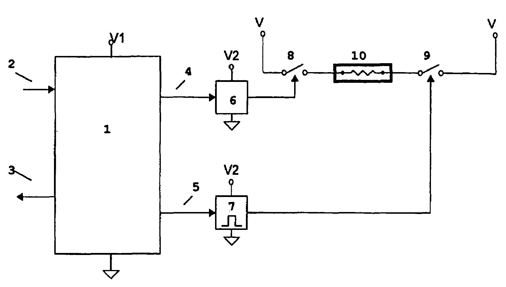
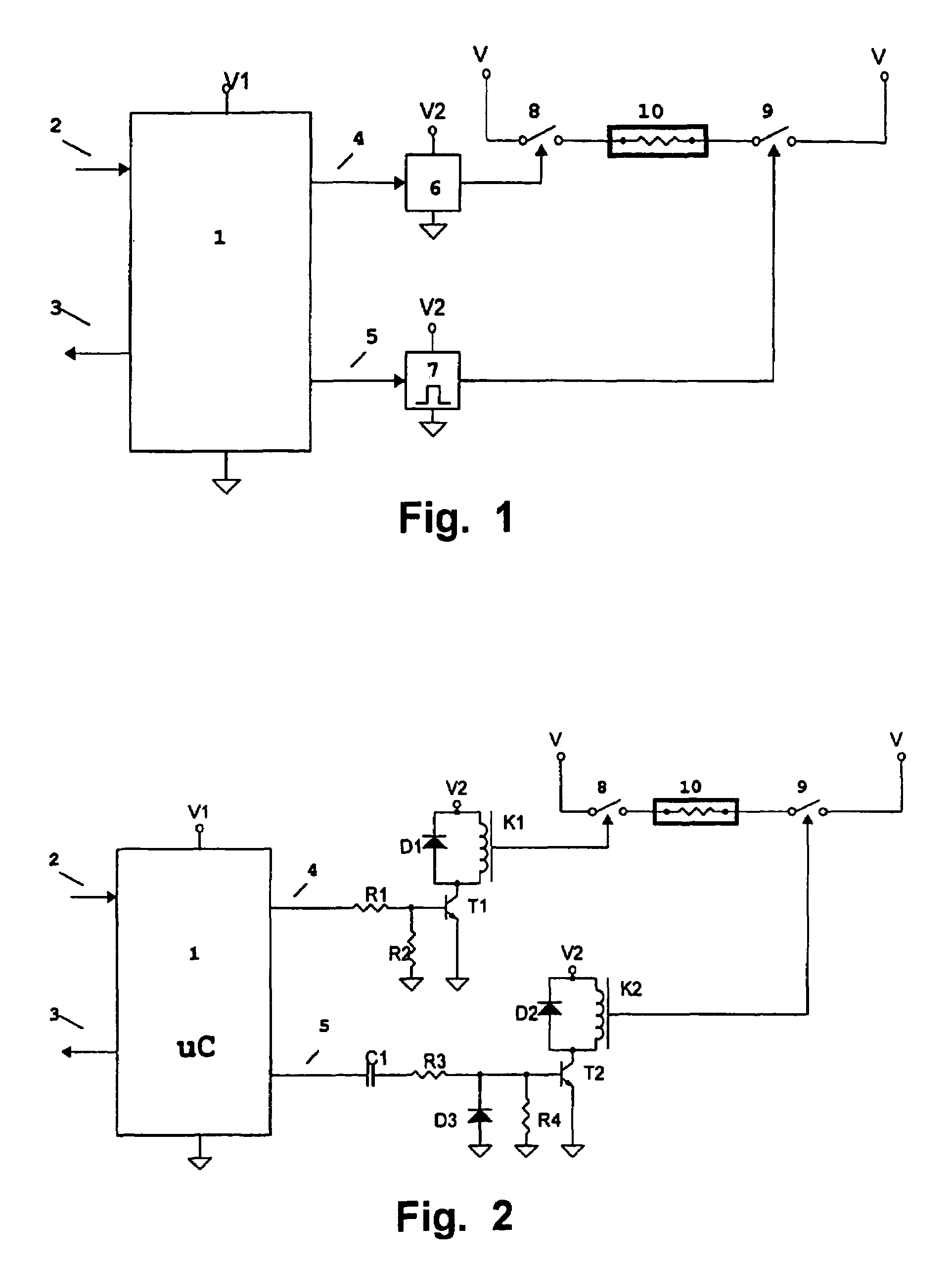
[0031]As is shown in FIG. 2, the operation switching means 8 comprise a power relay with a coil K1, and the drive circuit 6 comprises a transistor T1 connected in series with said coil K1. Said drive circuit 6 is completed with the resistors R1 and R2. The coil K1 is connected in parallel to a free-wheeling diode D1.

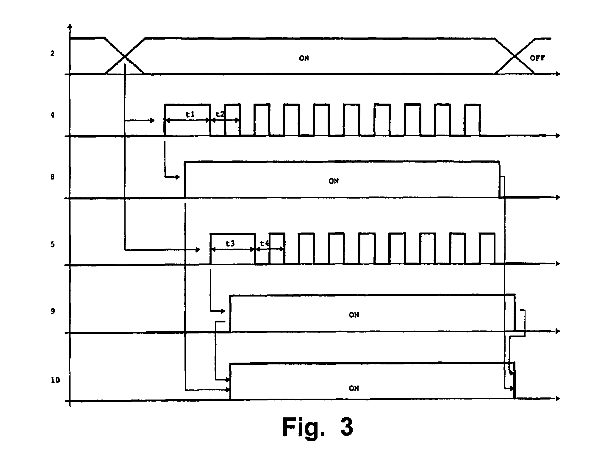
[0032]In a preferred embodiment, the first command signal 4 is also a pulse signal. With reference to FIG. 3, when the microprocessor receives an instruction signal 2 which involves the activation of the electrical load 10, the microprocessor generates the command signals 4 and 5. As is shown in said FIG. 3, in this embodiment both command signals 4 and 5 are pulse ...


PUM


Abstract

Failsafe control circuit for electrical appliances whereby at least one electrical load (10) is activated, the control circuit comprising logic control means (1), operation switching means (8) between said electrical load (10) and a supply voltage (V), and a first drive circuit (6) which receives a first command signal (4) from the logic control means (1), said first drive circuit (6) acting on said operation switching means (8). It also comprises security switching means (9) between the electrical load (10) and the supply voltage (V), and a second drive circuit (7) which receives a second command signal (5) from the logic control means (1), said second drive circuit (7) acting on the security switching means (9) so that it closes said security switching means (9) only if said second command signal (5) is a pulse signal.

Description

BACKGROUND OF THE INVENTION[0001]The present invention relates to control circuits for activating electrical loads of electrical appliances.[0002]Control systems for the activation of electrical loads in electrical appliances are known which comprise an electronic circuit that includes logic control means such as a microprocessor. It is important to guarantee that this type of control systems are safe against failures of the electronic circuit itself, and particularly against failures of the logic control means.[0003]U.S. Pat. No. 5,175,413 discloses a failsafe control system for operating a power relay to energize a resistive heating element in a cooking apparatus. The control system comprises a logic circuit, such as a microprocessor, with an output connected to a first branch which acts on a first transistor and a second branch which acts on a second transistor. The first and second transistors are both in series, and are also in series with the power relay. The first branch, whi...

Claims


Application Information

Patent Timeline
Patent Type & Authority Patents(United States)
IPC IPC(8): G05B9/02H03K19/007G05B19/042H01H47/00
CPCG05B9/02G05B19/0425H01H47/004G05B2219/23471G05B2219/21154H05B6/062
Inventor FERNANDEZ, GONZALOLANDA, EIDERAMORIZA, JOSE MIGUELMUGUERZA, ENEKO
Owner EIKA S COOP LTDA
Why Eureka
Try Eureka