Refrigerant system

a refrigerant system and refrigerant technology, applied in the direction of cooling fluid circulation, domestic cooling apparatus, lighting and heating apparatus, etc., can solve the problems of difficult use of oxygen and water as refrigerants in refrigeration cycles, low pressure of oxygen and water, and difficulty in handling, etc., to achieve the effect of convenient attachmen

Inactive Publication Date: 2007-08-07
SANYO ELECTRIC CO LTD
View PDF29 Cites 10 Cited by
  • Summary
  • Abstract
  • Description
  • Claims
  • Application Information

AI Technical Summary

Benefits of technology

[0016]A first object of the present invention is to solve the above-mentioned conventional problems or to provide a refrigerant system in which exhaust heat-exchanged by a gas cooler is caused to smoothly flow without stagnation, refrigerant gas is sufficiently cooled in the gas cooler, the durability of the compressor can be improved without causing an overload state and an increase in operation power of the compressor, and even if carbon dioxide is used as a refrigerant the generation of the sliding loss and leak loss and an air-cooling shortage of refrigerant gas in the gas cooler can be minimized.
[0017]A second object of the present invention is to solve the above-mentioned conventional problems or to provide a refrigerant system in which exhaust heat-exchanged by a gas cooler is caused to smoothly flow without stagnation, refrigerant gas is sufficiently cooled in the gas cooler, the durability of the compressor can be improved without causing an overload state and an increase in operation power of the compressor, and the heat-exchanging efficiency of an internal heat exchanger is improved and at the same time the generation of condensation on a surface of an outer side tube of the internal heat exchanger can be prevented, and even if carbon dioxide is used as a refrigerant the generation of the sliding loss and leak loss and an air-cooling shortage of refrigerant gas in the gas cooler can be minimized.

Problems solved by technology

However, when fluorocarbon is emitted into the atmosphere it has significant problems of the earth-warming effect, the ozone layer breakage and the like in large scale.
Among these natural refrigerants, oxygen and water are low in pressure and it is difficult to use them as refrigerants in refrigeration cycles.
Since ammonia and hydrocarbon are flammable, there is a problem that their handling is difficult.
Thus, air cooling of refrigerant gas in the gas cooler 6 becomes insufficient, resulting in an increase in the operation pressure.
As a result the compressor 5 reaches an overload state and problems arise that an operation power is increased, a protection device is actuated to stop the compressor and the durability of the compressor 5 is adversely affected whereby its useful life of is shortened.
Thus there is a problem that since the differential pressure easily generates sliding loss or leak loss and the refrigerant temperature is increased, the air cooling of the refrigerant gas in the gas cooler becomes more insufficient.

Method used


Image

  • Refrigerant system
  • Refrigerant system
  • Refrigerant system

Examples


first embodiment

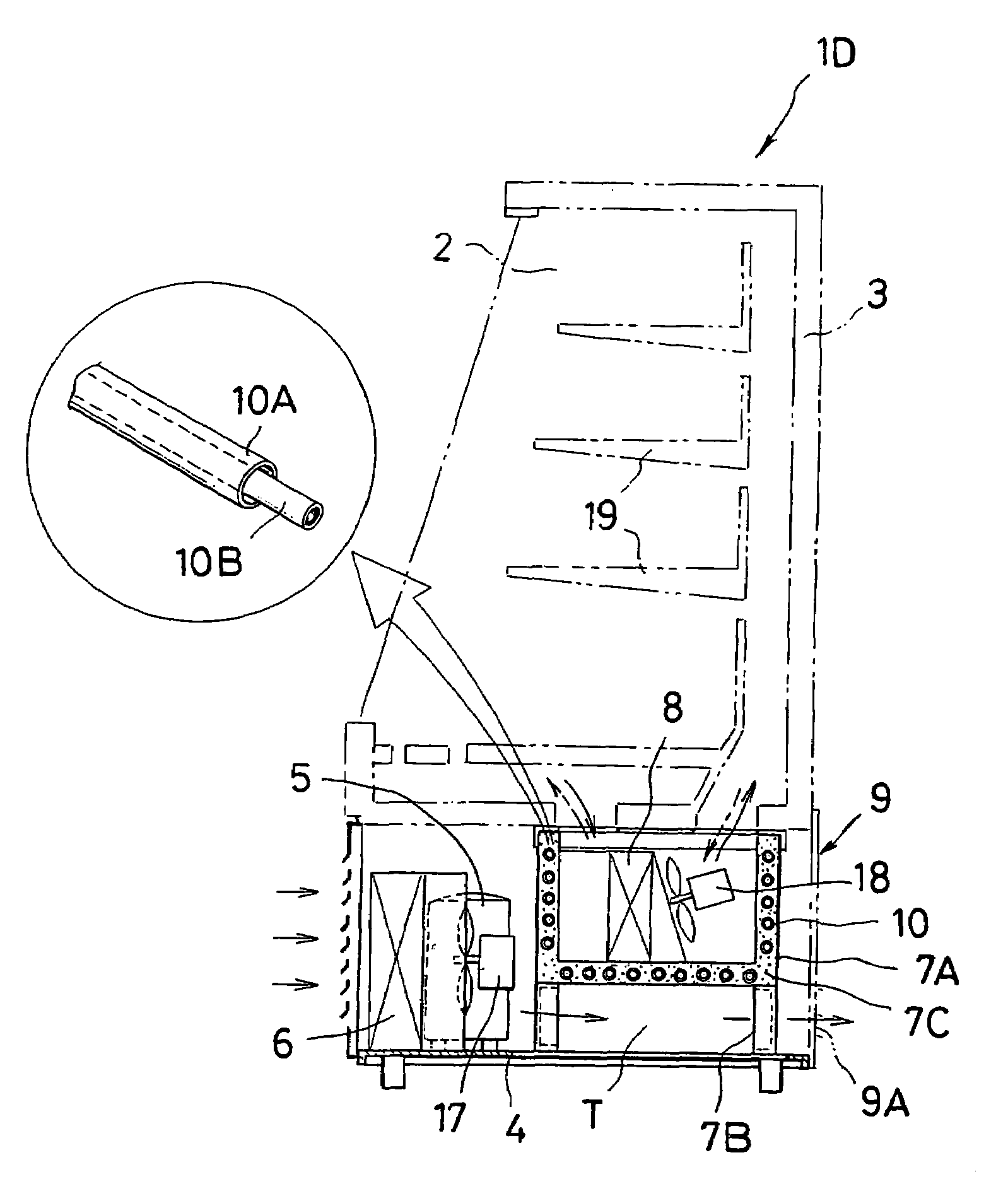
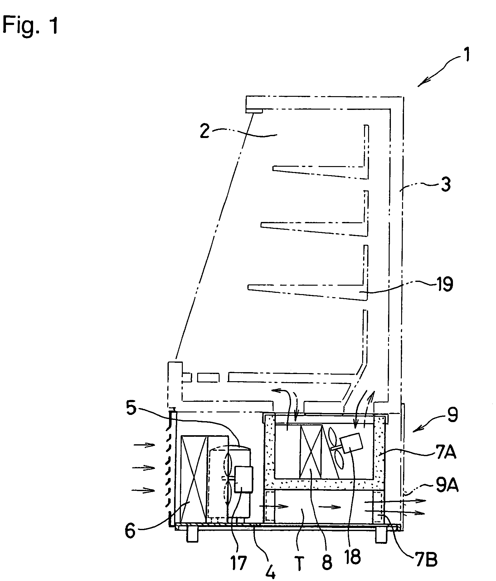
[0038]FIG. 1 is an explanatory cross-sectional view explaining one embodiment of a refrigerant system according to the present invention.

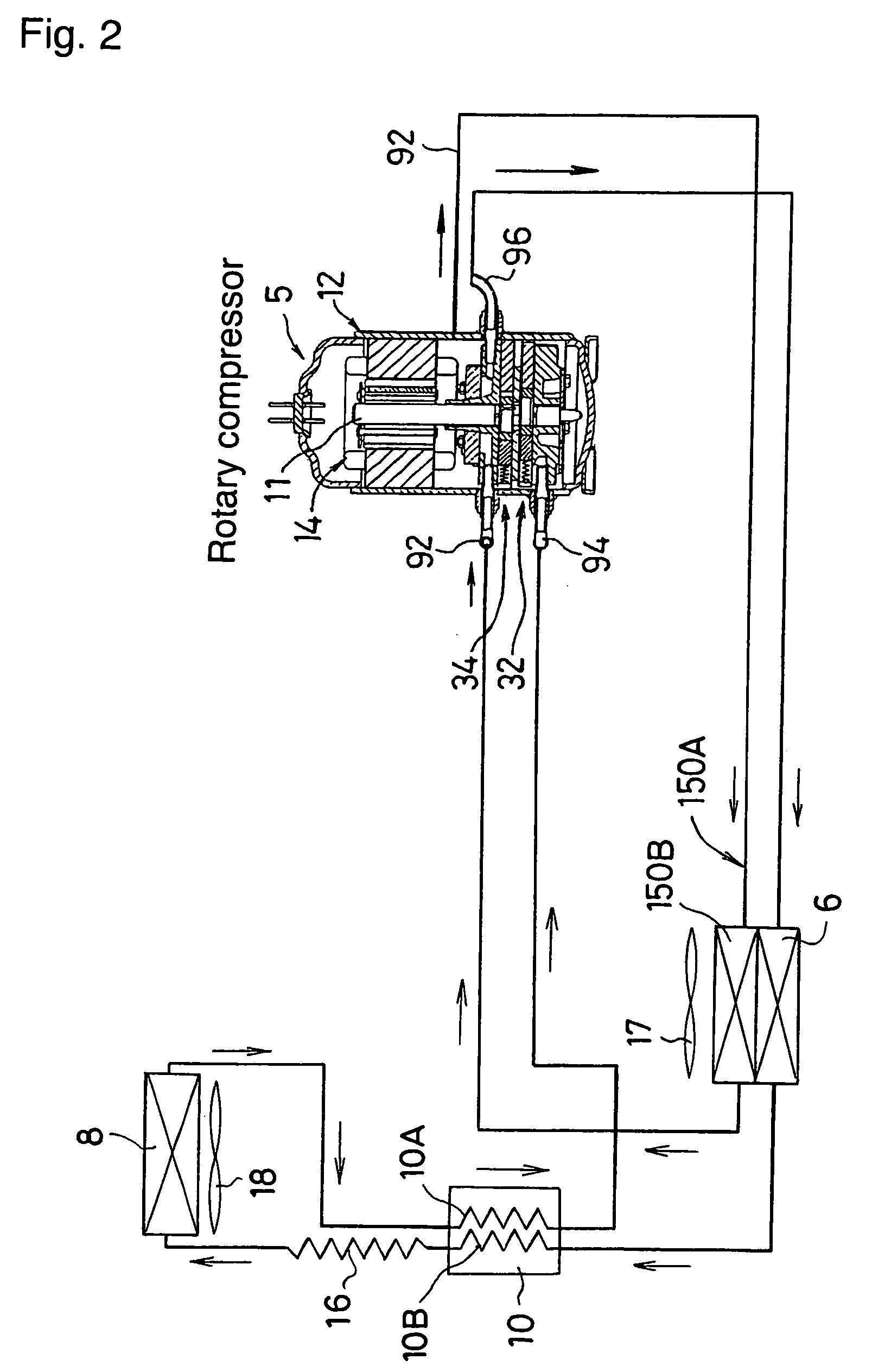
[0039]FIG. 2 is a refrigeration, circuit of the refrigerant system of the present invention.

[0040]FIG. 3 is a p-h diagram of the refrigeration circuit in FIG. 2.

[0041]It is noted that a refrigerant system of the present invention is used in a vending machine, a refrigerator, a showcase or the like.

[0042]A refrigerant system 1 (showcase) of the present invention comprises a heat insulating housing 3 provided with an accommodating space 2 inside, and a refrigeration unit 9 attached to a lower portion of the heat insulating housing 3, in which a compressor 5, a gas cooler 6, an internal heat exchanger 10, and a restriction means 16 are disposed on a unit base 4, a plurality of supporting columns 7B are fixedly provided on the unit base 4 at intervals, a heat insulating case 7A is set on the supporting columns 7B, an evaporator 8 accommodated in an ins...

second embodiment

[0054]FIG. 4 is an explanatory view explaining another refrigerant system according to the present invention.

[0055]In a refrigerant system 1B (showcase) shown in FIG. 4 a skeleton of a refrigeration unit 9 is formed by a combination of U-shaped frame members 21, 22, 23 and 24 as shown in FIG. 4, and fixing members 22A, 23A and 24A for fixing a heat insulating case 7A to predetermined positions of the frame members 22, 23 and 24 are provided.

[0056]On the other hand, fixing members 22B, 23B and 24B are provided at positions of the heat insulating case 7A corresponding to the fixing members 22A, 23A and 24A.

[0057]The fixing members 22B, 23B and 24B of the heat insulating case 7A are made to correspond with the fixing members 22A, 23A and 24A so that the heat insulating case 7A is set on the skeleton of the refrigeration unit 9, and are fixed by screws and the like not shown. The refrigerant system 1B is the same as the refrigerant system 1 of the present invention shown in FIG. 1 excep...

third embodiment

[0059]FIG. 5 is an explanatory view explaining a refrigeration unit of another refrigerant system according to the present invention.

[0060]A refrigeration unit 9 of a refrigerant system of the present invention shown in FIG. 5 is the same as in the refrigerant system 1 of the present invention shown in FIG. 1 except that elongated four exhaust passages 25 are penetratingly provided at positions of the unit base 4 corresponding to the portion of the air passage T through which most of exhaust heat-exchanged by the gas cooler 6 passes and the exhaust heat-exchanged by the gas cooler 6 passes through the exhaust passages 25 to be discharged outside.

[0061]The refrigeration unit 9 of the refrigerant system of the present invention has the same actions and effects as the refrigerant system 1 of the present invention. Further the exhaust heat-exchanged by the gas cooler 6 well flows without stagnation and passes through the exhaust passage 25 and exhaust outlet 9A, and can be discharged ou...


PUM


Abstract

A refrigerant system 1D comprises a heat insulating housing 3 provided with an accommodating space inside and a refrigeration unit 9 attached to a lower portion of the heat insulating housing 3, in which a compressor 5, a gas cooler 6, an internal heat exchanger 10, a restriction means 16 and an evaporator 8 accommodated in a heat insulating case 7A are disposed on a unit base 4. The gas cooler 6 and the heat insulating case 7A are disposed so that air heat-exchanged by the gas cooler 6 moves toward the heat insulating case 7A, an air passage T is provided between the unit base 4 and the heat insulating case 7A, the air heat-exchanged by the gas cooler 6 is passed through the air passage T to be discharged outside, and the internal heat exchanger 10 is disposed in such a manner that it is embedded in a heat insulating material layer 7C provided around the heat insulating case 7A to be provided with a heat insulation property. Accordingly, exhaust heat-exchanged by the gas cooler is discharged outside without stagnation, and increases in an overload and operation power of the compressor are suppressed and the durability of the compressor can be improved. Further, the heat-exchanging efficiency of the internal heat exchanger can be improved and the generation of condensation on a surface of an outer side tube of the internal heat exchanger can be prevented.

Description

[0001]This application claims priority to Japanese application No. 2004-032509 filed Feb. 9, 2004, and Japanese application No. 2004-032511 filed Feb. 9, 2004.BACKGROUND OF THE INVENTION[0002]1. Technical Field[0003]The present invention relates to a refrigerant system applicable to a vending machine, a showcase or the like, and more specifically relates to a refrigerant system comprising a heat insulating housing provided with an accommodating space, and a refrigeration unit, attached to a lower portion of said heat insulating housing and in which a compressor, a gas cooler, an internal heat exchanger, a restriction means and an evaporator are disposed on a unit base.[0004]2. Related Art[0005]FIG. 8 is an explanatory cross-sectional view of one example of a conventional refrigerant system. The conventional refrigerant system 1A (an example of a showcase) comprises a heat insulating housing 3 provided with an accommodating space 2 inside, and a refrigeration unit 9 attached to a low...

Claims


Application Information

Patent Timeline
Patent Type & Authority Patents(United States)
IPC IPC(8): A47F3/04F25B1/04F25B1/10F25B9/00F25B40/00F25D19/00F25D19/02F25D23/00F25D23/06
CPCF25B9/008F25D19/02F25D23/061F25D23/003F25B1/04F25B1/10F25B40/00F25B2309/061F25D2323/00271F25D2317/0651F25D2317/0661F25D2317/0684F25D2323/00264
Inventor YAMANAKA, MASAJIISHIGAKI, SHIGEYAMATSUMOTO, KENZOYAMASAKI, HARUHISAFUTAKAWAME, MIDORI
Owner SANYO ELECTRIC CO LTD
Why Eureka
Try Eureka