Power line communications system

a communication system and power line technology, applied in the direction of electric controllers, ignition automatic control, instruments, etc., can solve the problems of power loss, motor winding modification, and electric system not perfectly balanced

Inactive Publication Date: 2007-09-11
AUTONOMOUS WELL CO LTD THE +1
View PDF2 Cites 15 Cited by
  • Summary
  • Abstract
  • Description
  • Claims
  • Application Information

AI Technical Summary

Benefits of technology

[0030]Conveniently, the voltage differential between the supply neutral connection and load neutral connection may be created by use of a variable impedance placed in at least one conductor of the power line. Wherein the variable impedance is used to create an imbalance in the load, said impedance providing a means for controlling the potential difference exhibited between the supply neutral and load neutral.

Problems solved by technology

However, electrical systems are not perfectly balanced and for a motor powered over a long cable with various junction boxes and connectors, each phases impedance will be affected by a multitude of factors, such as: the length of the cable, the connection resistance, the position of the winding in the slot, the differences in winding lengths, the construction of the motor, the construction of the cable and the transposition of the cable.
Such imbalances in a load create a voltage difference between the two neutral points and as current flow between the two neutrals is undesirable as it will cause a loss of power and they are not typically connected.
However this type of system may require the need for modifying the motor windings.
This however requires a large coupling package at both the supply and the load neutral connection, which are designed to remove signals above a few Hertz to remove the known imbalance voltage differences and as such limits the data transfer rate to a few bits per second.
Furthermore, these types of coupled signals also suffer from the fact that they transfer less power to the transmitter.

Method used


Image

  • Power line communications system
  • Power line communications system
  • Power line communications system

Examples


Embodiment Construction

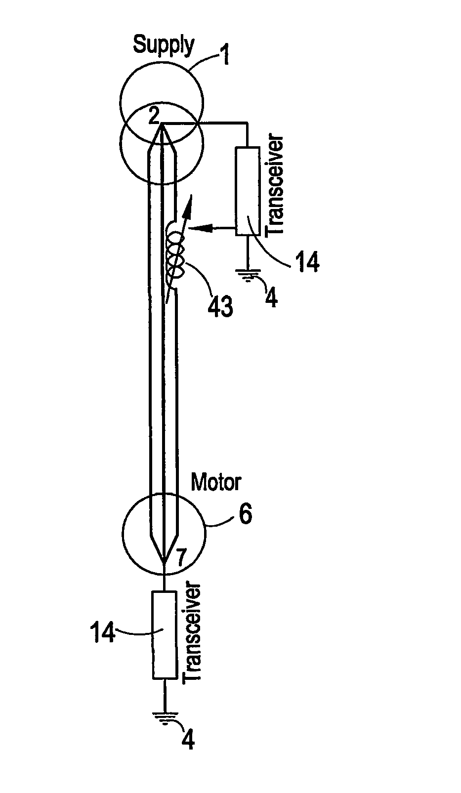
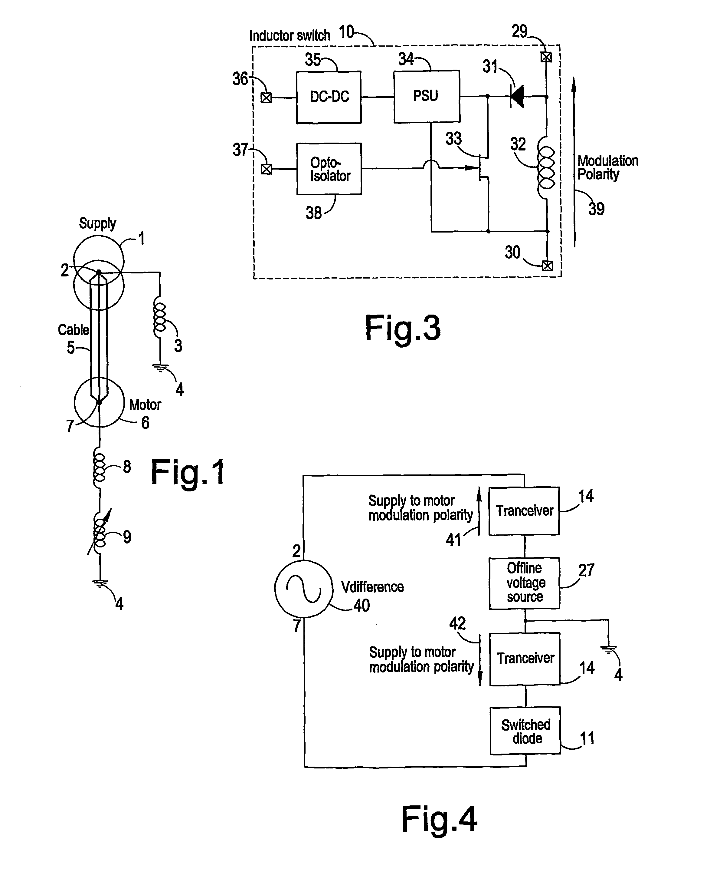
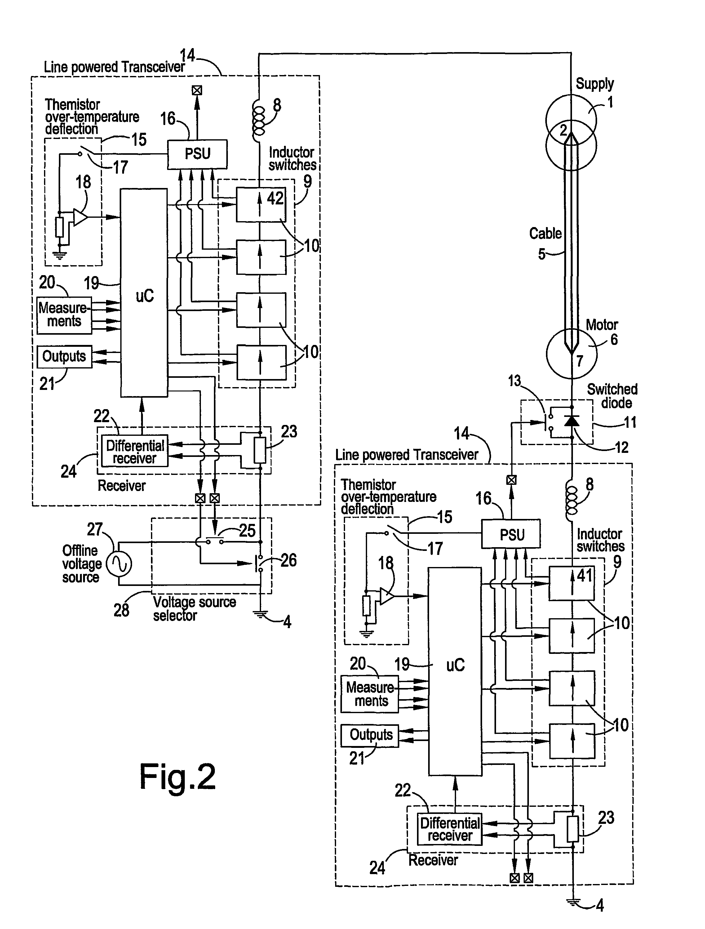
[0048]Referring to FIG. 1 there is shown a three phase, power source 1 supplying a remote motor 6 through a substantial length of power cable 5. The power source 1 having a neutral point 2 which is connected to an earth point 4 through a fixed value inductance 3. Whilst the motor 6 is connected in a star configuration creating a motor neutral point 7 which is connected to earth via a fixed inductance 8 and a variable inductance 9.

[0049]The voltage seen at the neutral point of the power supply 2 and the neutral point of the motor 7 are not equal. This is due to resistances in each conductor of the power cable 5, and the general construction details of the motor 6, which means the load is not perfectly balanced and hence will result in a voltage differential between the supply neutral connection and the load neutral connection. This resultant voltage is applied across the three inductors 3,8,9 via earth which results in a current flow through the inductors via earth, where Ohm's law d...


PUM


Abstract

A power line communications technique (PLC) is disclosed which allows communications across any three phase electric system by modulating the impedance through earth between any two points of differing voltage on the electrical system in order to use the power supply as the communications power source thereby using the power supply current as the communications carrier. No additional coupled communications source is required and modulation of an earth link current at the power frequency is especially suitable for remote electrical loads, such as an oil well electric submersible pump, where it is most cost effective to only have the three power conductors and no neutral nor signal wires in the power cable. Embodiments of the invention are described.

Description

FIELD OF THE INVENTION[0001]The present invention relates to a power line communication (PLC) system, wherein information is transmitted along a power conductor. The invention is particularly suitable for oil wells and general purpose waterlift pumps, where a load such as an electric submersible pump (ESP) is installed deep in an oil well, bore hole or caisson and where the remoteness of the load results in a technical and commercial obstacle to installing a separate communication cable.BACKGROUND OF THE INVENTION[0002]Within power line communication systems there is provided a 3 phase power supply to power a load. If this supply were to power a perfectly balanced load the voltage between the neutral point of the supply and the neutral point of the load would be 0 volts. Subsequently, if both the supply neutral and the load neutral were connected using a neutral wire or both were connected to earth, then the current flow in this neutral or earth link would be 0 amps.[0003]However, e...

Claims


Application Information

Patent Timeline
Patent Type & Authority Patents(United States)
IPC IPC(8): G05B11/01H04B3/54
CPCH04B3/54H04B2203/5466H04B2203/547H04B2203/5475H04B2203/5495
Inventor ROBERTSON, MARK PATRICK
Owner AUTONOMOUS WELL CO LTD THE
Why Eureka
Try Eureka