
Car flashlight structure
a flashlight and car body technology, applied in the direction of transportation and packaging, light and heating equipment, semiconductor devices of light sources, etc., can solve the problems of inability to use the overhead night light in the car interior for auxiliary illumination, many dead angles where the light does not illuminate, and the electric power required by the flashlight cannot be replenished, so as to achieve the effect of recharging electric power
- Summary
- Abstract
- Description
- Claims
- Application Information
AI Technical Summary
Benefits of technology
Problems solved by technology
Method used
Image

Examples
Embodiment Construction
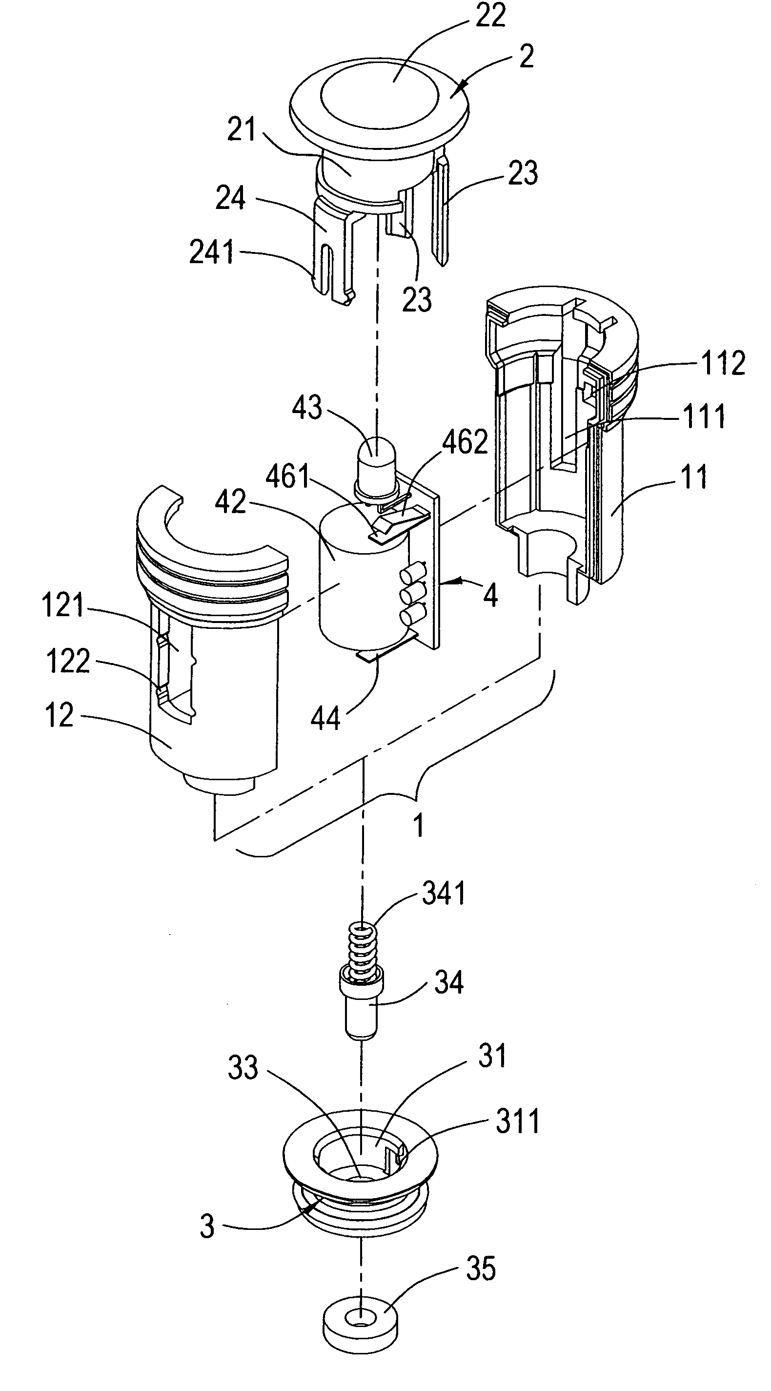
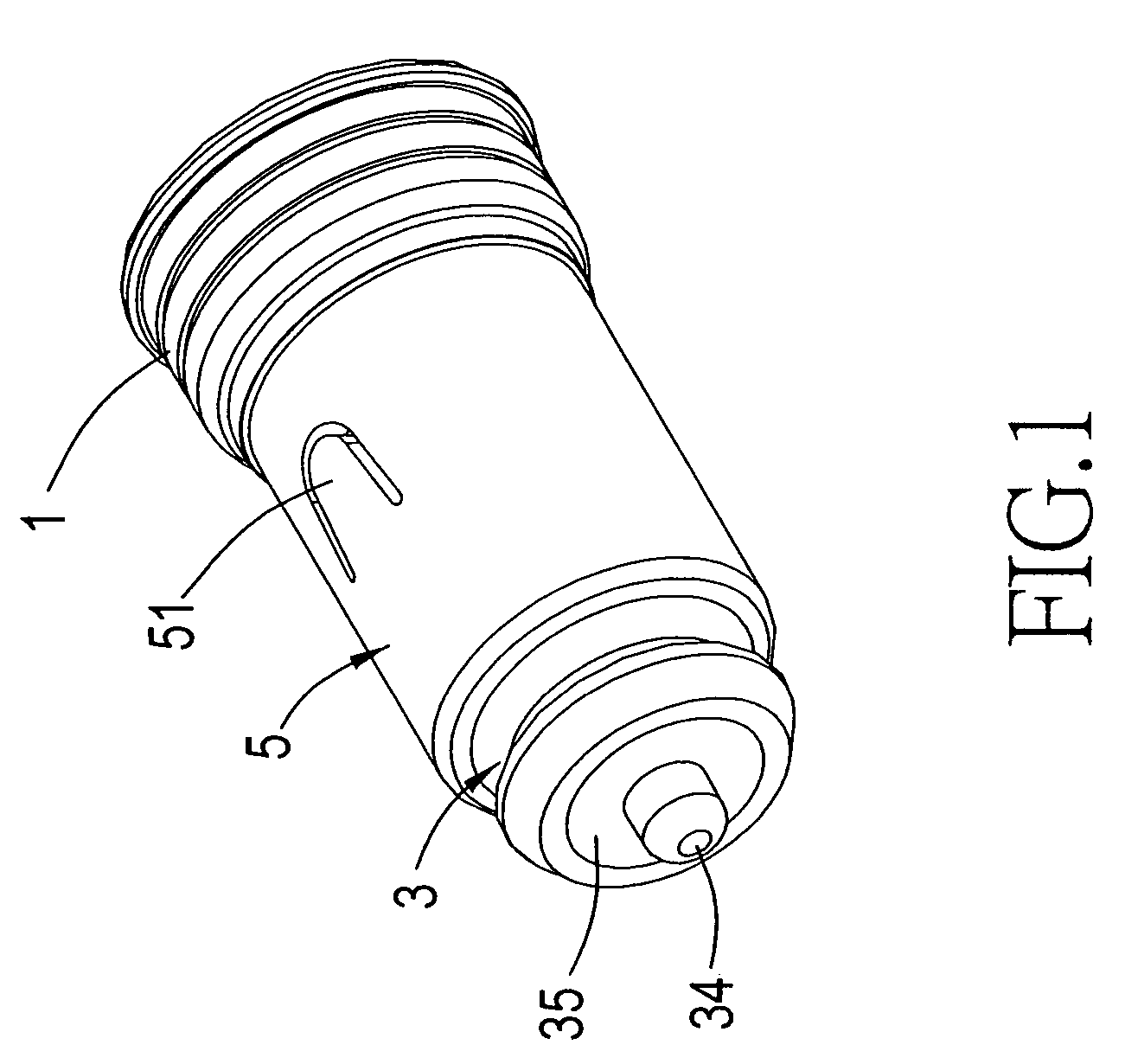
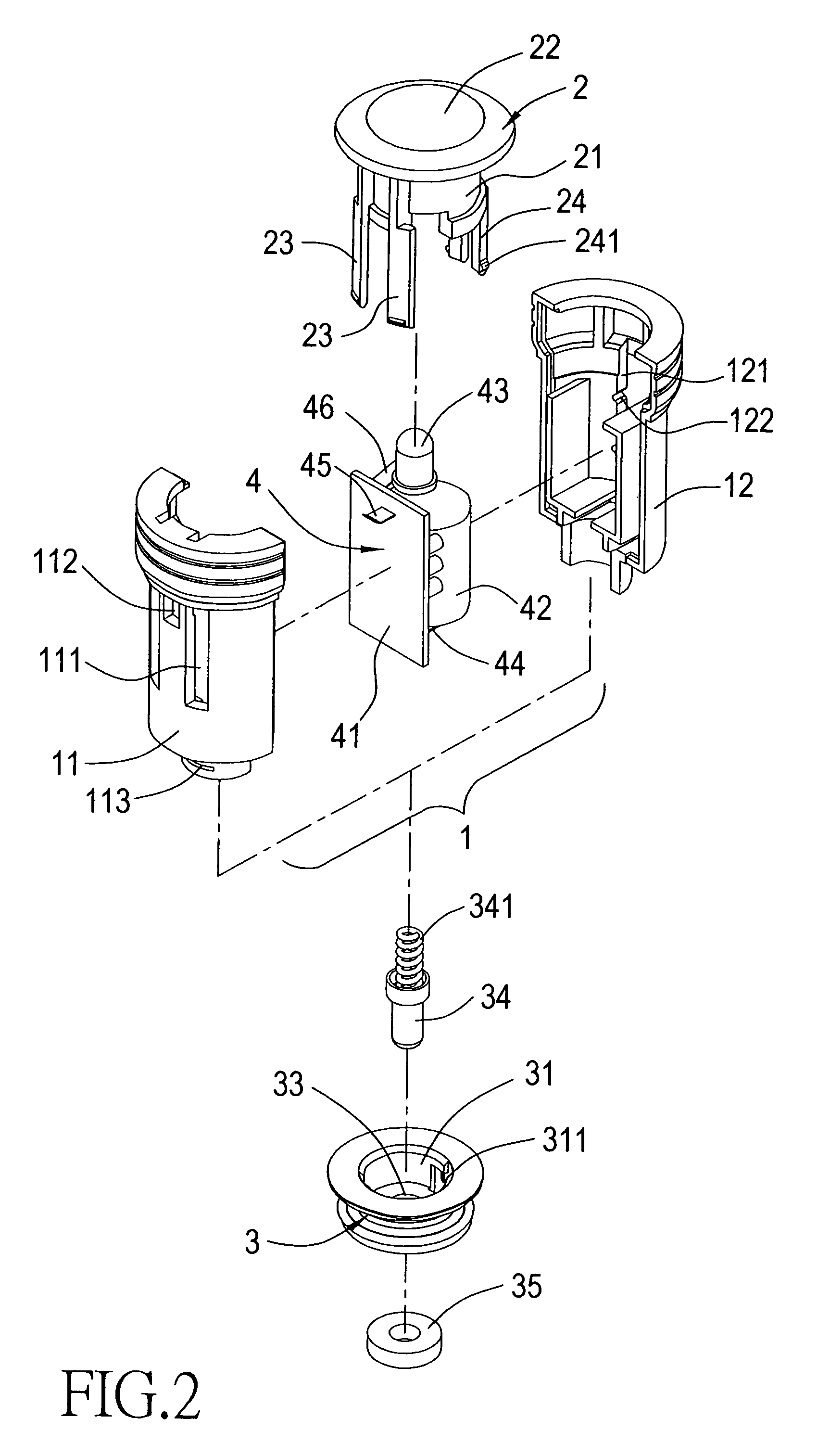
[0030]Referring to FIGS. 1, 2 and 3, which show the present invention structured to comprise a cylindrical body 1, a cap 2, a casing cover 3, an illumination assembly 4 and an outer cylinder 5.
[0031]Referring to FIGS. 2, 3 and 4, the cylindrical body 1 comprises a first casing 11 reciprocally combined with a corresponding second casing 12. At least one first slide track 111 is defined on a surface of the first casing 11, and at least one second slide track 121 is defined on a surface of the second casing 12. Moreover, a set of positioning grooves 122 are respectively defined on two ends within the second slide track 121, and a through hole 112 is defined at an appropriate position in the first casing 11. Furthermore, a protruding catch 113 is configured on a surface of a rear end of the first casing 11 of the cylindrical body 1.
[0032]Referring to FIGS. 2, 3, 7, 8, 9, 10, 14 and 15, the cap 2 is disposed on a front end of the aforementioned cylindrical body 1. The cap is provided wit...
PUM
 Abstract
Description
Claims
Application Information