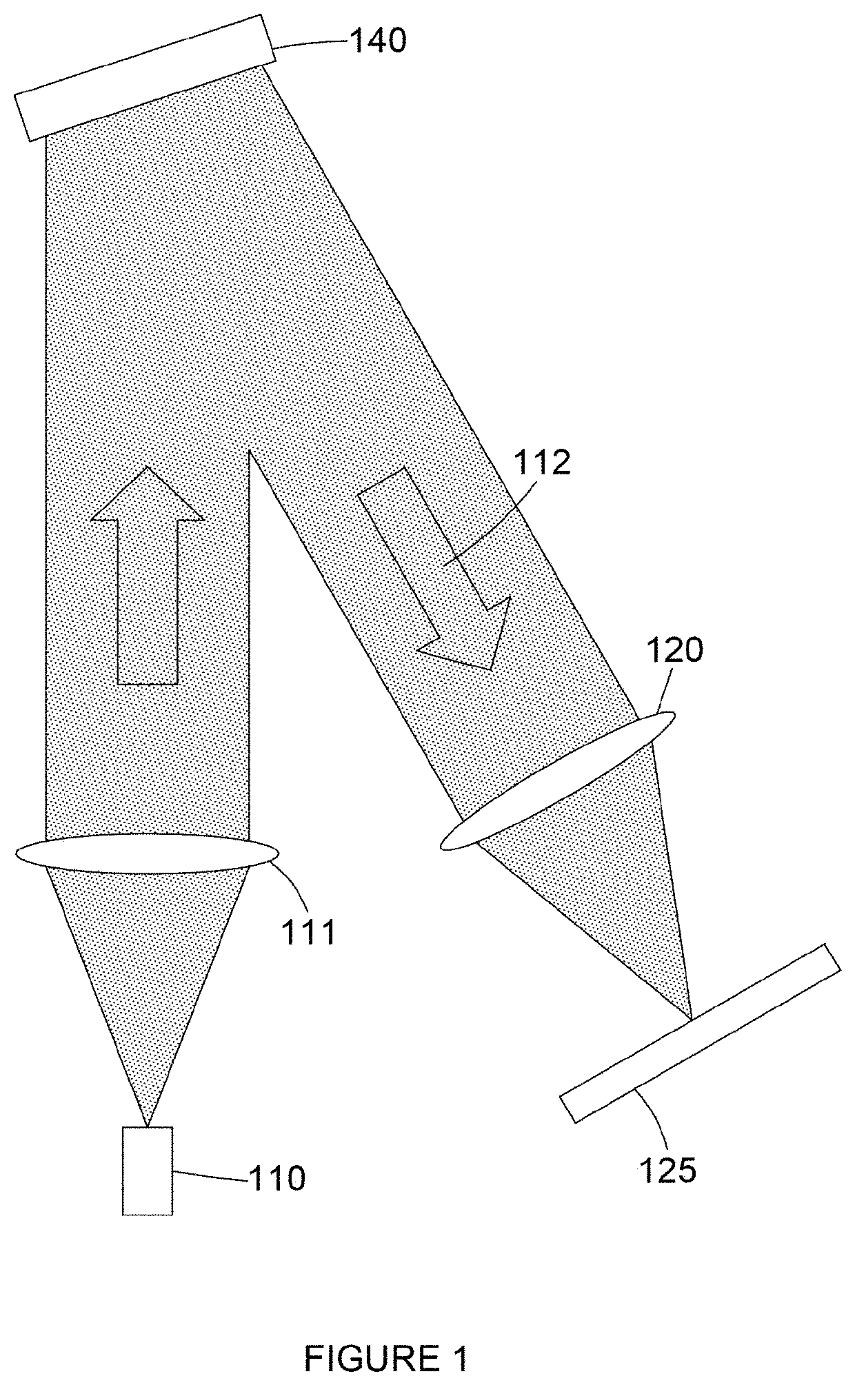
[0012]There is also provided a method of improving image quality in a head-up display. A first step of the method comprises displaying a computer-generated hologram on a spatial light modulator. A second step of the method comprises spatially-modulating light in accordance with the computer-generated hologram to form a holographic reconstruction corresponding to the picture on a screen. A third step of the method comprises transmitting light of the picture through a bandpass filter to an optical system. A fourth step of the method comprises forming a magnified image of the picture using at least one reflective element of the optical system having optical power. A fifth step of the method comprises reflecting light of other wavelengths received from the optical system using the bandpass filter. The bandpass filter is curved to form a convex surface receiving light from the optical system and a concave surface receiving light of the picture from the screen.
[0013]The bandpass filter protects the picture generating unit from sunlight which may get into the head-up display. This sunlight may be focused towards the picture generating unit by the optical system. Focused sunlight of sufficient power may cause damage to components of the picture generating unit such as the screen. The bandpass filter may be a notched filter comprising transmission bands (or notches) at wavelengths of the light of the picture. The bandpass filter is otherwise reflective to optical wavelengths including infrared, visible and ultra-violet wavelengths. The bandpass filter has a convex side and a concave side. The configuration of the bandpass filter provides two technical improvements. Firstly, the bandpass filter is arranged such that the convex side (or face) receives light, such as the sunlight, from the optical system. The convex side of the bandpass filter therefore disperses (or defocuses) the received sunlight in at least one direction to reduce the risk of damage to other components of the head-up display. Secondly, the bandpass filter is arranged such that the concave side (or face) receives the light of the picture from the screen. The concave side therefore reduces the range of incidence angles thereon which means that a bandpass filter with higher reflectivity to the sunlight may be used. The reflectivity of the bandpass filter may be increased because the width of the transmission bands may be decreased owing to the decreased range of incidence angles. Accordingly, in summary, the bandpass filter is safer and more effective at protecting the picture generating unit from sunlight. The bandpass filter in accordance with this disclosure may be parallel-faced (i.e. the convex side is substantially parallel to the concave side) and easily-formed by, for example, bending around a curved shape such as a cylinder.
[0014]The bandpass filter may be cylindrically or conically curved. The bandpass filter may be cylindrically or conically curved around an axis. The axis around which the bandpass filter is curved may be tilted with respect to the screen. The concave surface and the convex surface of the bandpass filter may both be cylindrical or conical. The method of improving image quality in a head-up display may therefore further comprise the sixth step of tilting the axis (about which the bandpass filter is cylindrically or conically curved) with respect to the screen.
[0015]The cylindrical curvature on the convex side provides the technical improvement of dispersing or defocusing any sunlight received from the optical system in only one direction. This is advantageous because it means the bandpass filter can be tilted, in the perpendicular direction, such that all sunlight is reflected off-axis. In other words, no sunlight is reflected by the bandpass filter back along the optical axis of the sunlight. The cylindrical surface described may be configured such that no part thereof is perpendicular to the optical axis of the received sunlight. In contrast, a spherically curved surface, for example, cannot be tilted with respect to the screen to reflect all received sunlight away from the optical system because, even if tilted, one point on the spherical surface will always be perpendicular to the optical axis of the received sunlight. Whilst the present disclosure extends to include more complex shapes which avoid this problem, the described cylindrical shape provides the technical improvement of being simple to fabricate.
[0016]The light of other wavelengths received by the bandpass filter from the optical system is converging owing to the optical power of the at least one reflective element and the light of the picture transmitted by the bandpass filter is diverging. Therefore, the bandpass filter may have a conical shape with sides that taper inwardly towards the screen. The bandpass filter intercepts a cone of sunlight propagating towards the picture generating unit. The bandpass filter may be tilted with respect to the screen. The sides of the bandpass filter may be tapered inwardly towards the screen in correspondence with the cone of sunlight. This provides the technical improvement of minimising the physical size of the bandpass filter. This may also provide the technical improvement of locally increasing the de-focusing power of the bandpass filter.
[0017]It is common to tilt the screen or display surface (i.e. the source image plane) of a picture generating unit to avoid veiling glare (that is, sunlight reflecting off the screen or display surface and reaching the viewer). However, tilting the display surface off-axis is not preferable because it can negatively affect image quality and impose limitations during the design process. There is disclosed herein a configuration which provides the technical improvement of not requiring the screen to be tilted. That is, the normal to the screen may be parallel with the input optical axis of the optical system.