Optical sectioning apparatus using advanced mirau optical interference microscopy

a technology of optical interference and optical sectioning, which is applied in the field of optical sectioning apparatus, can solve the problems of damage to the tissue structure, time-consuming pathologist's examination of frozen sections, and inability to guarantee the removal of tumors

Inactive Publication Date: 2019-05-02
ACUSOLUTIONS INC
View PDF6 Cites 0 Cited by
  • Summary
  • Abstract
  • Description
  • Claims
  • Application Information

AI Technical Summary

Benefits of technology

[0021]In one embodiment, the Mirau interference objective lens further includes an axial motion platform, and the sample carrier unit further includes a 3-D motion platform, so that by using the axial motion platform to move the Mirau interference objective lens, and using the 3-D motion platform to move the sample stained with a fluorescent dye, the information processing apparatus can derive a 3-D image of the sample accordingly.

Problems solved by technology

In conventional tumor surgery, it takes a lot of time for a pathologist to examine a frozen section to determine if a tumor is cleanly removed.
As a result, when the time allowed for the surgery is shorter than the time needed for the pathologist to complete the assessment of intraoperative pathological margin, the tumor cannot be guaranteed to be cleanly removed.
During the process of preparing a frozen section of a sample, if the sample contains much water, a formed crystal ice structure will cause a damage to the tissue structure of the sample; and if the sample contains much fat, the fat will remain unfrozen at temperatures around −20° C. where the other tissues are already frozen, and is therefore easy to slip off from the frozen section to cause an artifact to the frozen section.
However, there is still room for improvement in the performance of U.S. Pat. No. 9,185,357 B2, for example: (1) the system of U.S. Pat. No. 9,185,357 B2 uses two objective lenses and therefore requires more space for accommodating the two objective lenses and the cost will thereby be increased; (2) the antireflection film of the beam splitter generally has a low transmission rate for a UV band of wavelengths shorter than 400 nm.

Method used


Image

  • Optical sectioning apparatus using advanced mirau optical interference microscopy
  • Optical sectioning apparatus using advanced mirau optical interference microscopy
  • Optical sectioning apparatus using advanced mirau optical interference microscopy

Examples


Embodiment Construction

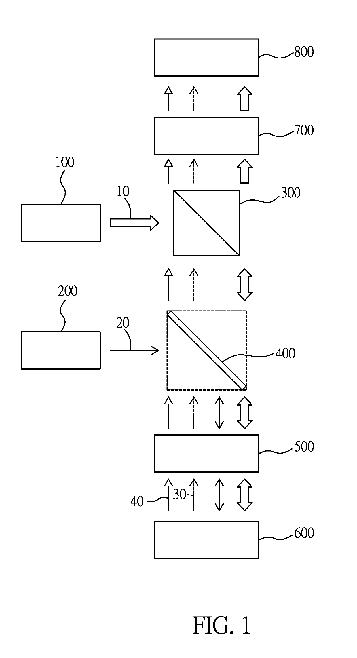
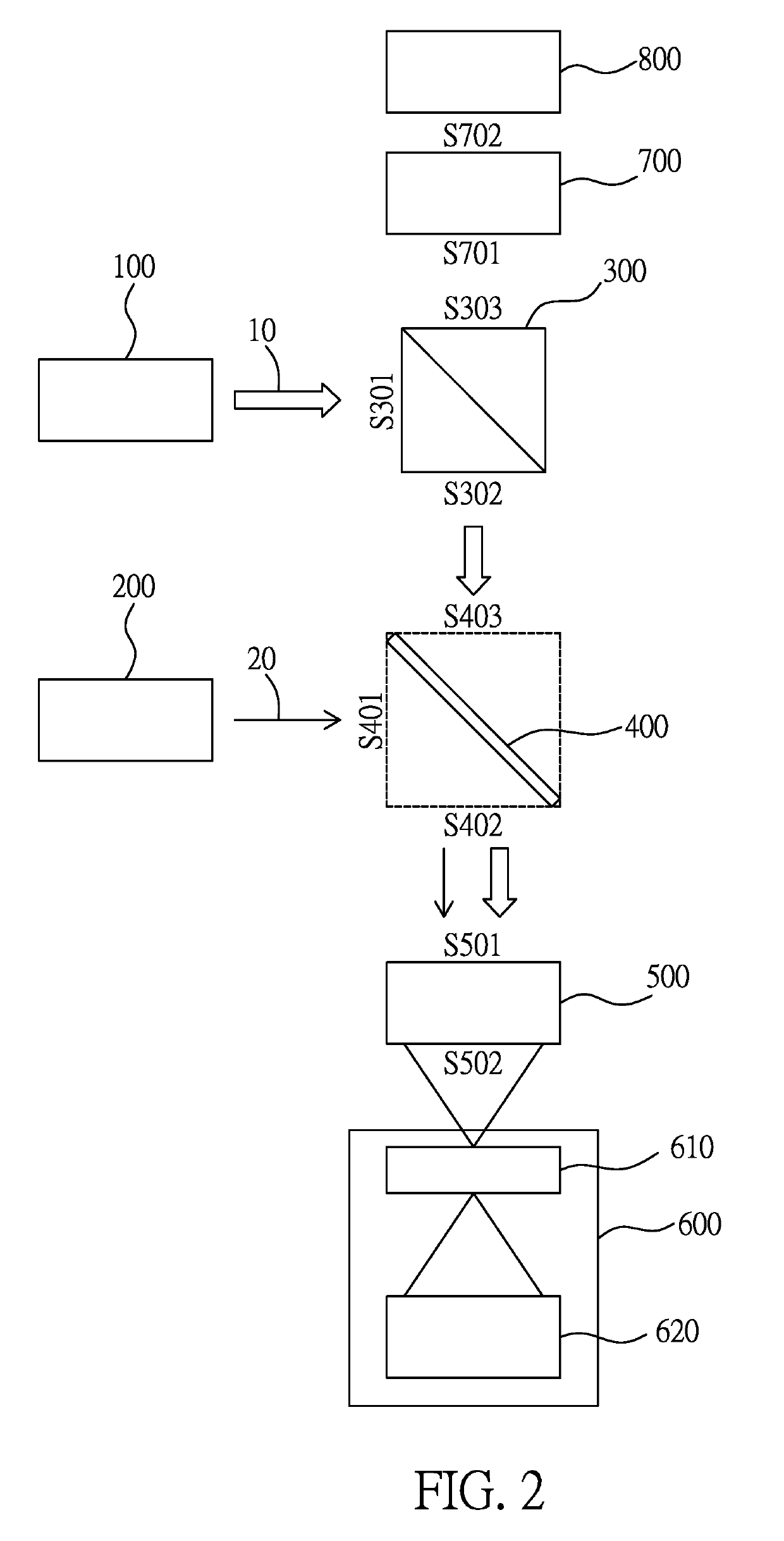
[0036]Please refer to FIG. 1-2, in which, FIG. 1 illustrates a block diagram of an optical sectioning apparatus combining Mirau optical interference microscopy and fluorescence microscopy according to one embodiment of the present invention, and FIG. 2 illustrates a beam splitting operation and a focusing operation of the optical sectioning apparatus of FIG. 1.

[0037]As illustrated in the figures, the optical sectioning apparatus combining Mirau optical interference microscopy and fluorescence microscopy includes: a wide band light source apparatus 100, a short wavelength light source apparatus 200, an optical circulator 300, a first dichroic splitter400, a Mirau optical interference objective lens 500, a sample carrier unit 600, a projection lens 700, and a sensor unit 800.

[0038]The wide band light source apparatus 100 is used to generate a wide band light beam 10 (indicated by a hollow arrow); the short wavelength light source apparatus 200 is used to generate a short wavelength li...


PUM


Abstract

An optical sectioning apparatus combining Mirau optical interference microscopy and fluorescence microscopy, including: a wide band light source; an optical circulator, facing the wide band light source for splitting an incident light beam into a reflected light beam and a transmitted light beam; a short wavelength light source; a first dichroic splitter, facing the short wavelength light source and the optical circulator respectively, and being capable of providing a light-blocking effect on a band of wavelengths shorter than a preset wavelength; a Mirau interference objective lens, having a collimated side facing the first dichroic splitter; a sample carrier unit facing a focal side of the Mirau interference objective lens; a projection lens, having a light entrance side facing the optical circulator; and a sensor unit facing a light exit side of the projection lens.

Description

BACKGROUND OF THE INVENTIONField of the Invention[0001]The present invention relates to an optical sectioning apparatus, especially to an optical sectioning apparatus combining Mirau optical interference microscopy and fluorescence microscopy.Description of the Related Art[0002]In conventional tumor surgery, it takes a lot of time for a pathologist to examine a frozen section to determine if a tumor is cleanly removed. As a result, when the time allowed for the surgery is shorter than the time needed for the pathologist to complete the assessment of intraoperative pathological margin, the tumor cannot be guaranteed to be cleanly removed.[0003]During the process of preparing a frozen section of a sample, if the sample contains much water, a formed crystal ice structure will cause a damage to the tissue structure of the sample; and if the sample contains much fat, the fat will remain unfrozen at temperatures around −20° C. where the other tissues are already frozen, and is therefore e...

Claims


Application Information

Patent Timeline
Patent Type & Authority Applications(United States)
IPC IPC(8): G02B21/04G02B21/16G02B21/00G02B21/06
CPCG02B21/04G02B21/16G02B21/0092G02B21/06G01B9/02041G01B9/02091G02B21/14G02B21/367
Inventor HSU, KUANG-YUTSAI, CHIEN-CHUNG
Owner ACUSOLUTIONS INC
Why Eureka
Try Eureka