Toner container

a technology for toner containers and containers, applied in the field of toner containers, can solve the problems of mixers interfering with the filling of toner, difficult to handle containers, and increasing the size of toner containers, and achieve the effect of convenient pulling ou

Active Publication Date: 2007-11-27
KK TOSHIBA +1
View PDF13 Cites 21 Cited by
  • Summary
  • Abstract
  • Description
  • Claims
  • Application Information

AI Technical Summary

Benefits of technology

[0011]The present invention is made in view of the above circumstances. It is a first object of the present invention to provide an easy-to-use toner container that can be easily pulled out from an image forming apparatus.
[0012]It is a second object of the present invention to provide a toner container that can be easily filled with toner.
[0013]It is a third object of the present invention to provide a toner container that can reduce the amount of toner remaining when the toner container is replaced.
[0031]According to the present invention, the toner container can be easily pulled out from the image forming apparatus. Consequently, the toner container can be easily handled when being replaced. Moreover, the present invention can reduce the amount of toner remaining when the toner is replaced.

Problems solved by technology

However, this increases the size of the toner container.
However, in pulling out the toner container, it is difficult to handle the container simply by using such a handle as described in the above publication.
Further, with a conventional toner container, if the filling port is located on the axis of the mixer, the mixer interferes with the filling of toner.

Method used


Image

  • Toner container
  • Toner container
  • Toner container

Examples


Embodiment Construction

[0051]Description will be give of embodiments for carrying out the present invention.

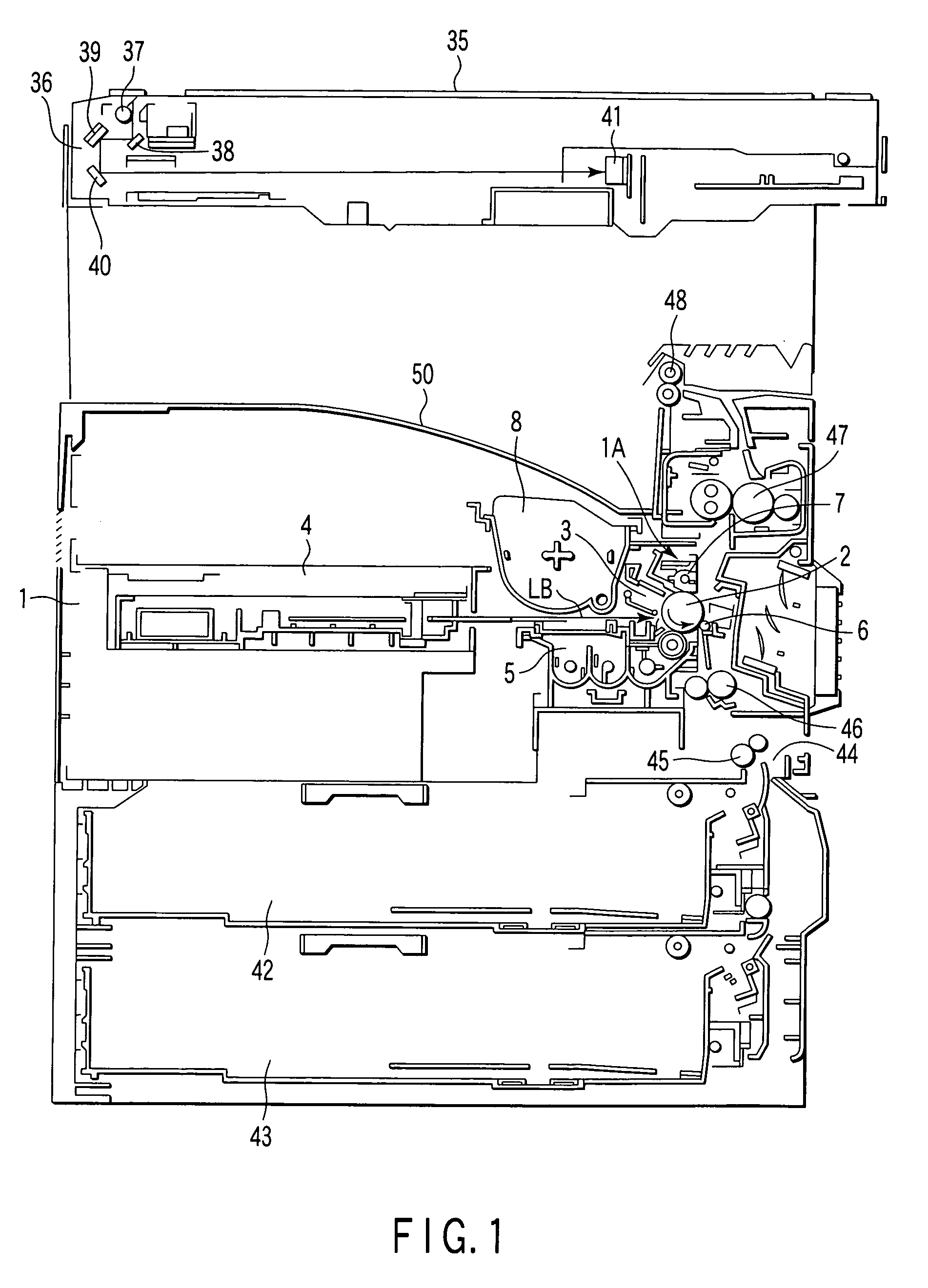
[0052]First, with reference to FIG. 1, description will be given of the internal structure of an electrophotographic copier according to an embodiment of the present invention.

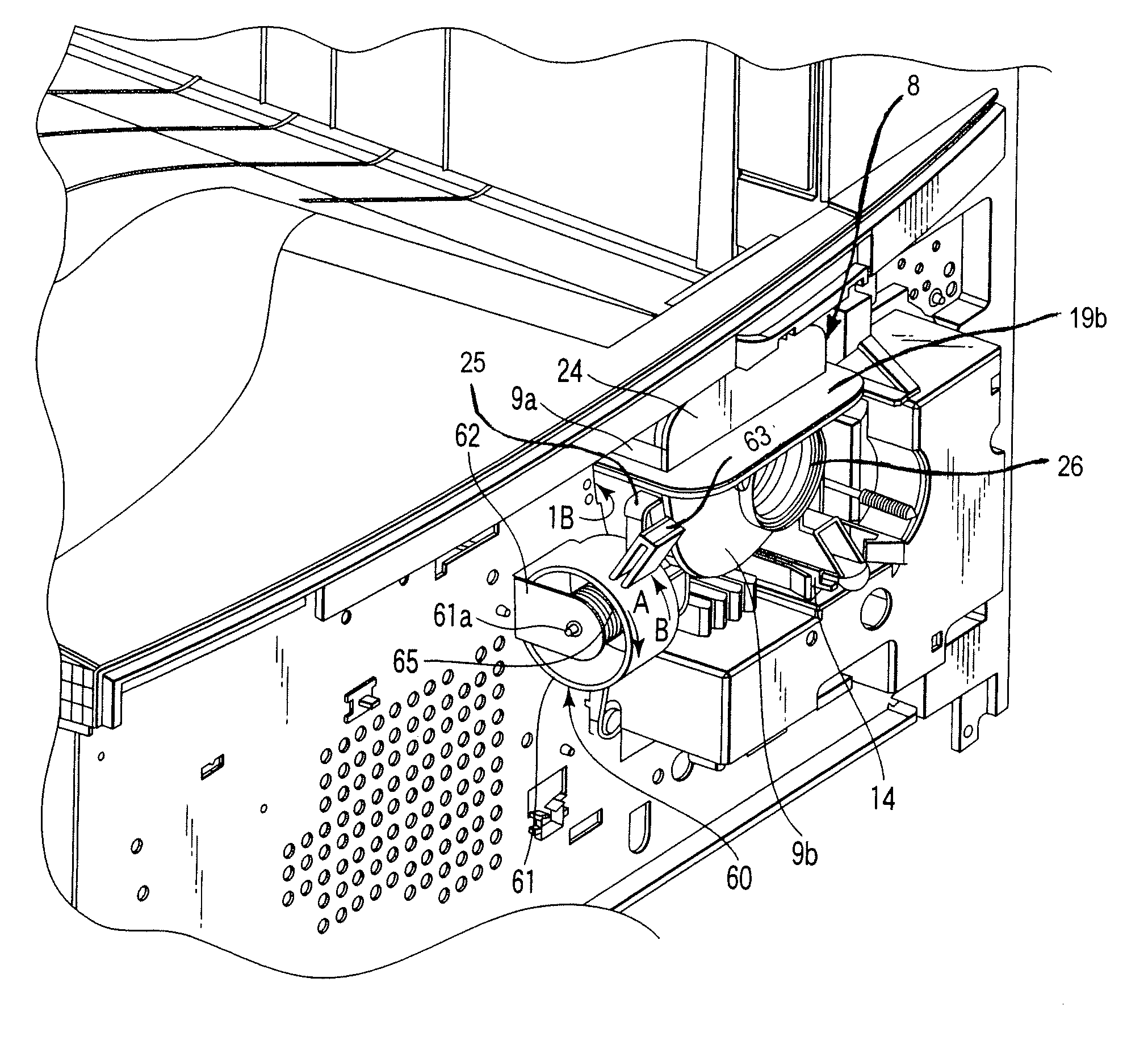
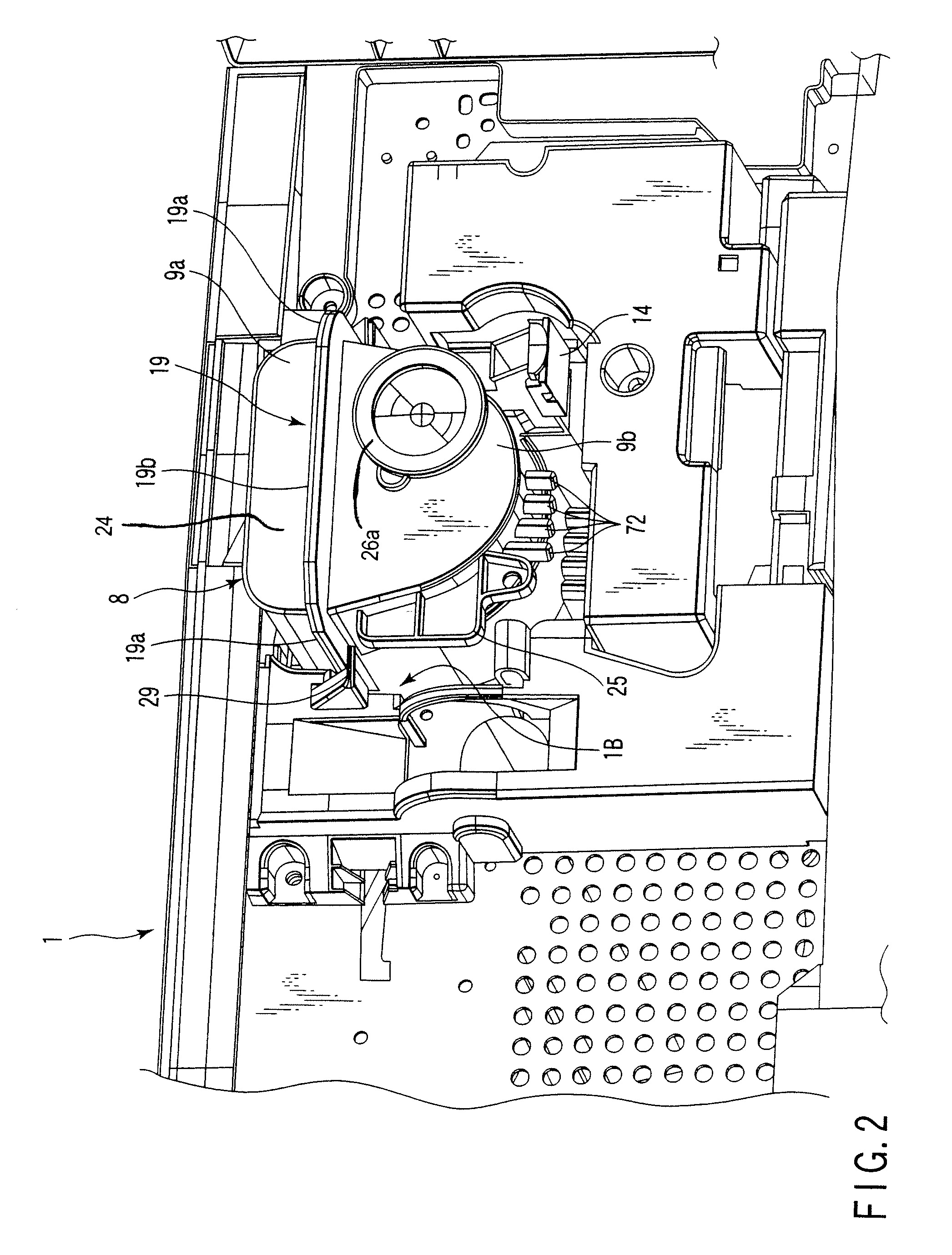
[0053]FIG. 1 is a schematic diagram showing the internal structure of the electrophotographic copier according to an embodiment of the present invention. FIG. 2 is an enlarged perspective view showing an essential part of a copier main body 1 according to the embodiment.

[0054]As shown in FIGS. 1 and 2, the electrophotographic copier has the copier main body 1 (image forming apparatus), having an image forming section 1A provided on one side of the interior of the center of the copier main body 1. The image forming section 1A comprises a photosensitive drum 2 that can rotate in a direction shown by an arrow in the figures. The following components are disposed around the photosensitive drum 2 along the rotating direction of the...


PUM


Abstract

A toner container installed in an image forming apparatus includes a toner container main body having a predetermined length and in which toner is accommodated, a discharge port through which the toner is discharged from the toner container main body, a shutter which opens and closes the discharge port, a handle provided on the toner container main body, and a pressed portion provided on the toner container main body and which is pressed by the image forming apparatus to project the handle out from the image forming apparatus.

Description

CROSS-REFERENCE TO RELATED APPLICATIONS[0001]This application is based upon and claims the benefit of priority from prior Japanese Patent Application No. 2004-208981, filed Jul. 15, 2004, the entire contents of which are incorporated herein by reference.BACKGROUND OF THE INVENTION[0002]1. Field of the Invention[0003]The present invention relates to a toner container used to supply toner to an image forming apparatus.[0004]2. Description of the Related Art[0005]Image forming apparatuses have a toner container used to supply toner to a developing device. The toner container is detachably installed in the image forming apparatus so that when the toner in the toner container is exhausted, a user can replace the toner container. A handle is commonly attached to the toner container so as to facilitate handling of the toner container during replacement (see, for example, Jpn. Pat. Appln. KOKAI Publication No. 2004-21063).[0006]The toner container is provided with a filling port through whi...

Claims


Application Information

Patent Timeline
Patent Type & Authority Patents(United States)
IPC IPC(8): G03G15/08
CPCG03G15/0832G03G15/0855G03G15/0865G03G15/0875G03G15/0886G03G2215/0665G03G2215/068G03G2215/0692G03G2215/0827Y10S222/01G03G2215/085G03G15/0867
Inventor KIMURA, HISASHIAMANO, TAKAFUMI
Owner KK TOSHIBA
Why Eureka
Try Eureka