Seal device

a seal device and sealing technology, applied in the field of sealing devices, can solve the problems of time and effort, complicated assembly of the sealing device, etc., and achieve the effects of reducing the time for assembling the sealing device, reducing the separation distance between the mating ring and the rotary shaft, and reliably fitting

Inactive Publication Date: 2021-05-06
EAGLEBURGMANN JAPAN
View PDF0 Cites 1 Cited by
  • Summary
  • Abstract
  • Description
  • Claims
  • Application Information

AI Technical Summary

Benefits of technology

[0009]It may be preferable that the guide portion of the set ring is inserted into the mating ring in a tightened state. According to this preferable configuration, the inner diameter center of the set ring and the inner diameter center of the mating ring are aligned with each other, and therefore, the inner diameter center of the mating ring and the diameter center of the rotary shaft can be aligned with each other. Thus, centering adjustment for the mating ring is not necessary, and the time for assembling the seal device can be shortened.
[0010]It may be preferable that the guide portion of the set ring has a first annular plate part brought into contact with an inner peripheral surface of the seal ring and formed continuously in a circumferential direction. According to this preferable configuration, the strength of the first annular plate part is held, and therefore, the set ring can be reliably fitted in the seal ring.
[0011]It may be preferable that the guide portion of the set ring has a second annular plate part inserted into the mating ring, and the second annular plate part is thicker than the first annular plate part. According to this preferable configuration, a separation distance between the mating ring and the rotary shaft can be increased, and contact of the mating ring with the rotary shaft upon operation can be prevented. Further, the first annular plate part is relatively thin, and a difference in pressure-wrapping force of the seal ring in a state in which the set ring is pressure-wrapped around the seal ring is small. Thus, the set ring is easily pulled out of the seal ring. In addition, the second annular plate part is relatively thick, and therefore, the strength of the set ring itself is increased.
[0012]It may be preferable that the set ring is provided with a pull portion for pulling the set ring in an axial direction departing from the casing. According to this preferable configuration, the set ring can be easily pulled out of the seal ring in a state in which the set ring is fitted onto the rotary shaft with the set ring penetrating the mating ring and being fitted in the seal ring.
[0013]It may be preferable that the mating ring is fastened to the casing by fastening means, and the casing, the mating ring, the seal ring, and the set ring are be unitized. According to this preferable configuration, the seal device including the casing in advance can be unitized, and therefore, assembly of the seal device can be facilitated.
[0014]It may be preferable that at least one split line extending in an axial direction is be formed at the set ring. According to this preferable configuration, the set ring is split in a C-shape or divided into multiple portions. Thus, in a state in which the set ring is fitted onto the rotary shaft with the set ring penetrating the mating ring and being fitted in the seal ring, the seal ring can be detached from the rotary shaft in an outer diameter direction after having slid in the mating ring direction, and therefore, detachment of the set ring is facilitated.

Problems solved by technology

However, due to uneven coating with the lubricant and poor handling in movement, the seal ring is easily twisted or rolled up at a press-fitting step until being housed in the recessed portion inside the casing, and the process of moving the seal ring to a given position of the rotary shaft without tilting of the posture of the seal ring takes time and effort.
This leads to a problem that assembly of the seal device is extremely complicated.

Method used


Image

  • Seal device
  • Seal device
  • Seal device

Examples


embodiment

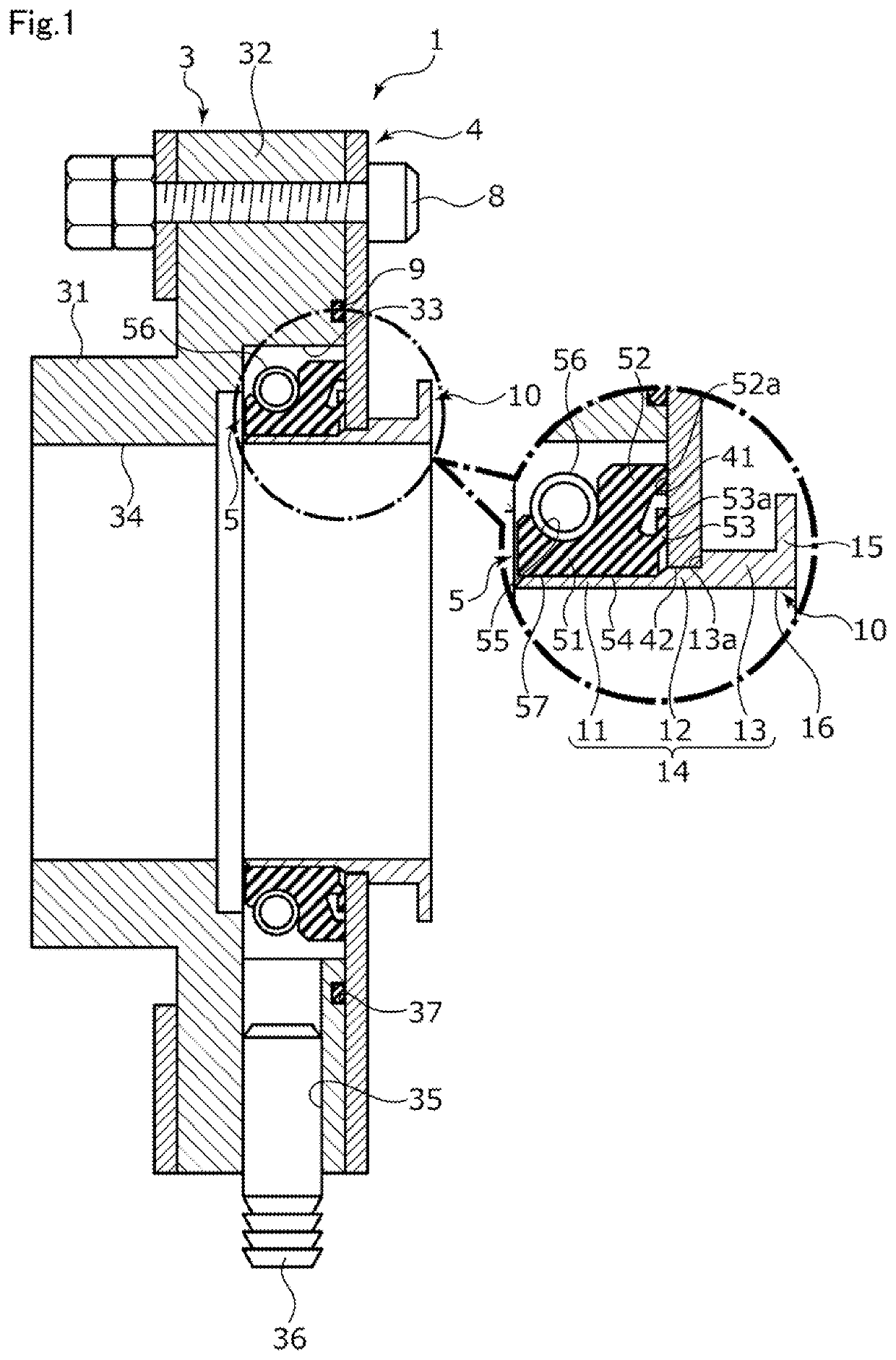
[0024]A seal device according to an embodiment will be described with reference to FIGS. 1 to 8. Hereinafter, in the present embodiment, a left side in the plane of paper of FIG. 1 will be described as a stern side or a casing side, and a right side in the plane of paper will be described as a bow side or a mating side.

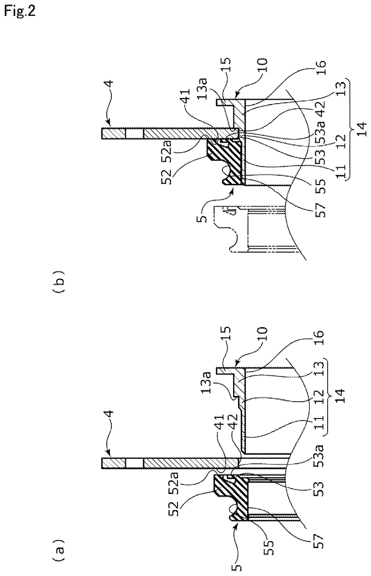
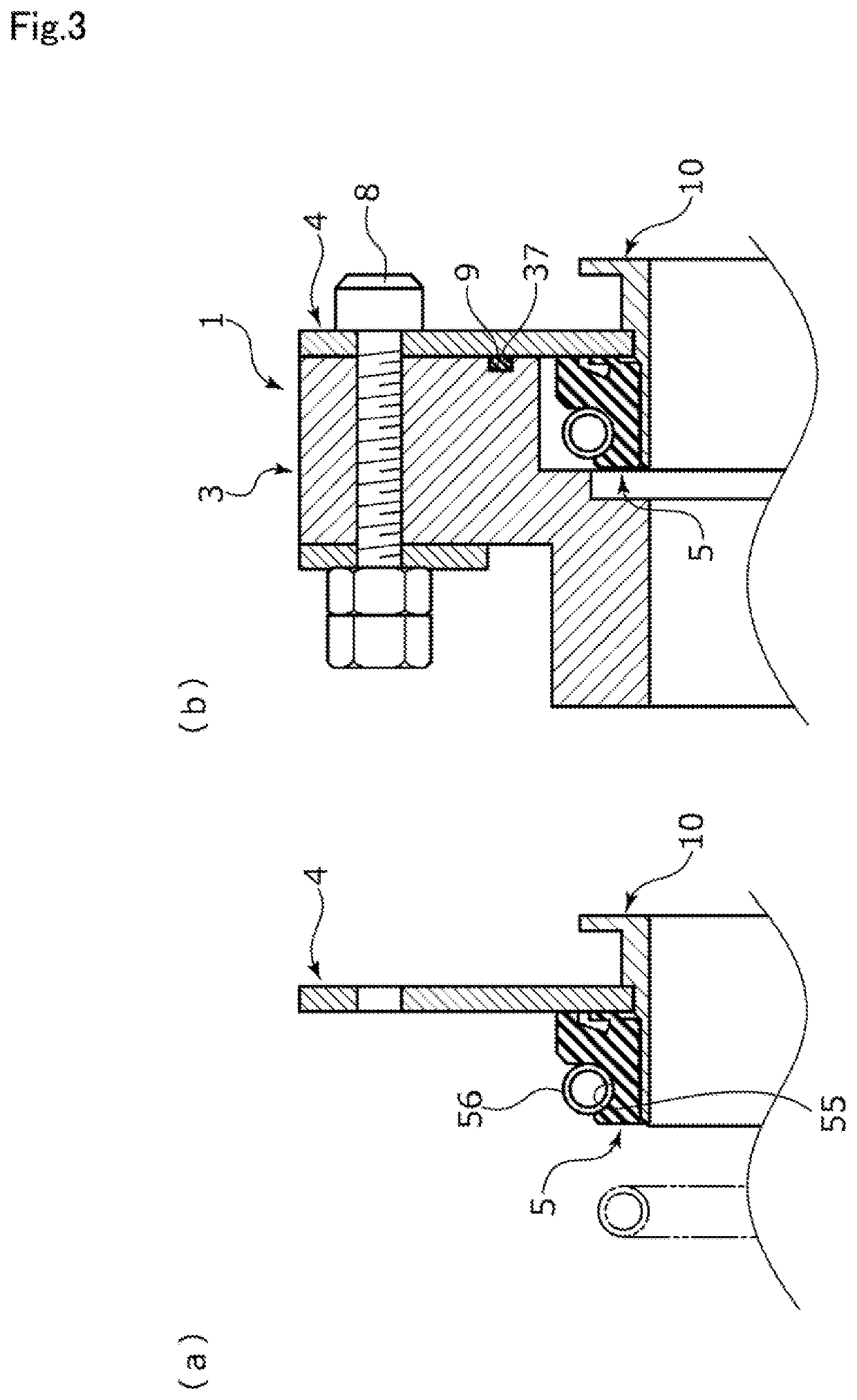
[0025]A seal device 1 is applied to a stern tube as cylindrical fluid equipment through which a rotary shaft 2 connecting a propeller and a motor of a ship penetrates. As illustrated in FIG. 1, the seal device 1 includes a casing 3, a mating ring 4 fixed to a bow-side side end of the casing 3, a seal ring 5 fitted onto the rotary shaft 2 upon use, and a set ring 10 (see FIG. 5A) detachably fitted in the mating ring 4 and the seal ring 5. The casing 3, the mating ring 4, the seal ring 5, and the set ring 10 can be temporarily unitized by the set ring 10. Note that the fluid equipment is not limited to one used for the ship, but may be fluid equipment used for, e.g., an...


PUM


Abstract

A seal device includes a casing, a mating ring, a seal ring provided in a recessed portion formed between the casing and the mating ring; and a set ring provided with a guide portion and a rotary shaft penetration portion on a radially inner side of the guide portion, the guide portion of the set ring being inserted into an opening of the mating ring and inserted, in a pressure-wrapped state, into an opening of the seal ring by elasticity of the seal ring.

Description

BACKGROUND OF THE INVENTIONField of the Invention[0001]The present invention relates to a seal device, and particularly relates to a seal device which can be applied to ships, boats and so forth.Description of the Related Art[0002]A seal device is configured to rotatably seal a portion between a casing and a rotary shaft arranged to penetrate the casing in fluid equipment. Such a seal device is often used among various types of fluid equipment and external air, and is also utilized for, e.g., a propeller shaft extending from the inside of a ship into water.[0003]JP 2005-214293 A (see pages 6 and 7, FIG. 1) discloses a seal device mainly including a casing connected to a stern tube in a ship body, a mating ring fixed to a bow side of the casing and having a sliding surface on a stern side, and a seal ring as an end surface seal attached and fitted onto the rotary shaft, having a sliding surface on the bow side, and formed slidable on the mating ring. Such a seal device is attached to...

Claims


Application Information

Patent Timeline
Patent Type & Authority Applications(United States)
IPC IPC(8): F16J15/3268F16J9/12
CPCF16J15/3268F16J9/12F16J15/3456B63H23/321F16J15/3272
Inventor NAKAMURA, RYO
Owner EAGLEBURGMANN JAPAN
Why Eureka
Try Eureka