Radio-controlled clock and method for gaining time information

a radio-controlled clock and time information technology, applied in the direction of clocks, synchronous motors, instruments, etc., can solve the problems of noise signals, noise signals, noise signals, etc., and achieve the effect of reducing noise and nois

Inactive Publication Date: 2008-01-08
ATMEL GERMANY +2
View PDF58 Cites 1 Cited by
  • Summary
  • Abstract
  • Description
  • Claims
  • Application Information

AI Technical Summary

Benefits of technology

[0052]The functional components for the present automatic amplification adjustment can be advantageously part of a logic circuit, particularly of a hardwired logic circuit. This applies particularly to the control and evaluation unit, to the counter and / or a shift register which all may be advantageously part of a logic circuit for example an FPGA circuit or a PLD circuit. Alternatively, these circuits may be implemented with a micro-controller which is typically part of a radio-controlled clock anyway. However, it is the special advantage of the invention that the required circuits can easily be realized separately, thereby not requiring a high powered micro-controller. Particularly, taking into account the AGC-critical second impulses and correspondingly modifying the automatic amplification adjustment can easily be realized in a circuit technical sense a logic circuit arrangement which leaves the micro-processor available for other purposes such as decoding and evaluating the received time signal and the handling of disturbances in the time signal as well as other specific tasks.
that the required circuits can easily be realized separately, thereby not requiring a high powered micro-controller. Particularly, taking into account the AGC-critical second impulses and correspondingly modifying the automatic amplification adjustment can easily be realized in a circuit technical sense a logic circuit arrangement which leaves the micro-processor available for other purposes such as decoding and evaluating the received time signal and the handling of disturbances in the time signal as well as other specific tasks.

Problems solved by technology

Without such automatic gain control adjustment always the same amplification would be used, which would lead to an undesirable over-control or an under-control.
A problem exists with received time signals because frequently noise signals are superimposed on the time signals.
Such noise signals can, for example be caused by electromagnetic radiation of electric and electronic equipment within the transmission range of the time signal transmitter to the time signal receiver.
Such noise signals may also be caused by the electric components of the time signal receiver itself.
In this connection the use of an automatic gain control would follow with its amplification in an undesirable manner the time signal change caused by the noise signal.
The problem is particularly seen in that depending on the type and size of the noise signal, a faulty receipt of the time signals may be involved.
The term “faulty receipt” means that during the duration of a received minute protocol erroneous binary decisions are being made which lead to a faulty evaluation of at least one data bit of the minute protocol.
A purposeful application of this method to a particular second impulse or a particular data bit within the minute protocol is, however, not possible.
Another problem results when the protocol of the transmitted time signal provides second impulses of rather long duration.
An unnecessary larger amplification leads to distortions of the signal in the receiver at the next second impulse because the closed loop control voltage and thus the automatic AGC adjustment is no longer at the mean value of the received time signal that is necessary for the field strength of the received time signal.
The sensitivity reduction in turn will result in a reduced receiver range of the radio-controlled clock and such reduced range will be noticeable by the user of the clock.
A further problem is seen in that the duration of the next following second impulse can be recognized as being faulty which in turn leads to faulty interpretations that, in the worst scenario, can lead to a faulty decoding.
However, the required software would be extraordinarily costly, particularly with regard to the storage capacity required for the software.
Such software solution would not be effective in connection with a time signal amplitude change that is caused by a second impulse.
Such a micro-controller does not provide the required dynamic for an effective influencing of the feedback control voltage or at least it would only be of limited use.
More specifically, a complete implementation by software for controlling the closed loop feedback voltage is only possible with such a micro-controller to a very limited extent because the requirements exceed the capabilities of a four-bit micro-controller.
Costs prohibit the use of a more powerful micro-controller in connection with radio-controlled clocks.

Method used


Image

  • Radio-controlled clock and method for gaining time information
  • Radio-controlled clock and method for gaining time information
  • Radio-controlled clock and method for gaining time information

Examples


Embodiment Construction

[0058]In the drawings all equivalent or functionally equivalent elements and signals are designated with the same reference characters unless otherwise indicated.

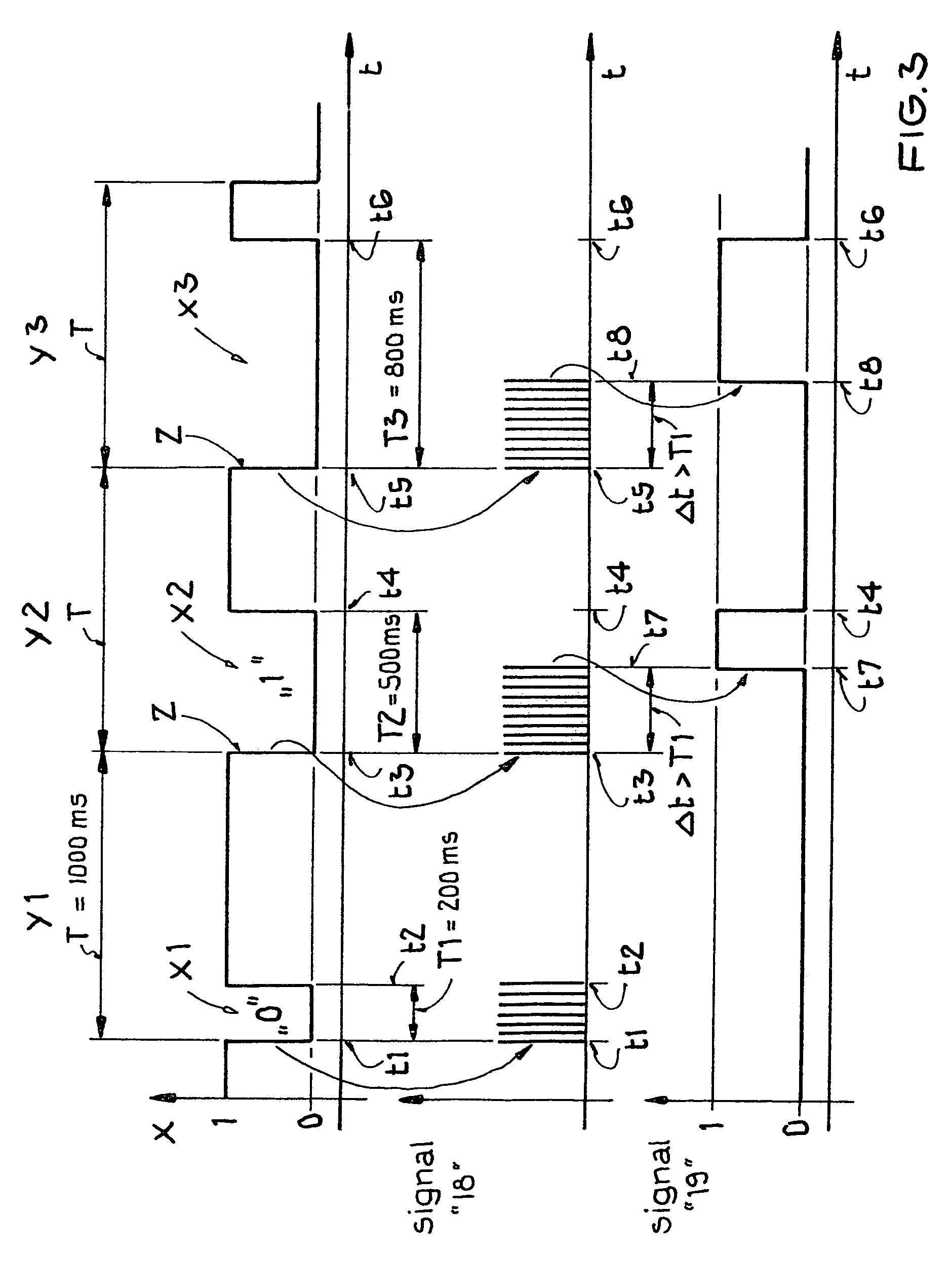
[0059]FIG. 3 shows a portion of a time signal transmitted by the United States time signal transmitter WWVB. This time signal diagram is used for explaining the invention. It should be noted that the illustration of FIG. 3 is not suitable for reproducing a special encoding. FIG. 3 is merely shown as an example. Further, the scale along the time axis t has been enlarged to provide a better overview.

[0060]FIG. 3 shows three complete time frames Y1, Y2 and Y3 of the time signal X. The duration of each time frame is exactly T=1000 msec. The time signal X transmitted by the US time signal transmitter WWVB comprises three different second impulses for the binary encoding. These second impulses represent amplitude reductions. More specifically, first amplitude reductions X1 have a duration of T1=200 msec. Second amplitude reductio...


PUM


Abstract

Time signals for controlling a radio clock are transmitted by a transmitter and received by a receiver as amplitude modulated time signals, formed of a multitude of time frames. Each time frame has a constant duration. These time signals are first automatically amplified. A so-called telegram of at least one received time signal is stored in a memory. At least one change of an amplitude of a time signal is determined in advance or predetermined and such amplitude change has a duration that is longer than a given or determined duration (Δt). When a predetermined amplitude change begins the automatic amplification is locked-in. The present circuit arrangement for operating a radio-controlled clock is equipped with components for performing the foregoing operations.

Description

CROSS-REFERENCE TO RELATED APPLICATION[0001]This application is related to U.S. application Ser. No. 11 / 057,030 filed on Jan. 28, 2005. The entire disclosure of the related application is incorporated herein by reference.PRIORITY CLAIM[0002]This application is based on and claims the priority under 35 U.S.C. §119 of German Patent Application 10 2004 004 411.2, filed on Jan. 29, 2004, the entire disclosure of which is incorporated herein by reference.FIELD OF THE INVENTION[0003]Time information is retrieved from received amplitude modulated time signals transmitted by a time signal transmitter. The received information is used to operate a radio-controlled clock or a receiver circuit for such a clock.BACKGROUND INFORMATION[0004]The radio-controlled transmission of time information is performed by transmitting so-called time signals by respective transmitters referred to herein as time signal transmitters. The term “time signal” is intended to mean a transmitter signal of short durati...

Claims


Application Information

Patent Timeline
Patent Type & Authority Patents(United States)
IPC IPC(8): H04B1/06G04G5/00G04G7/00G04R20/10H03F3/38H04B7/00
CPCG04G5/002G04R20/10
Inventor HAEFNER, HORSTPOLONIO, ROLANDSAILER, HANS-JOACHIM
Owner ATMEL GERMANY
Why Eureka
Try Eureka