Apparatus and method for controlling feed-forward amplifiers

a technology of amplifiers and amplifiers, applied in amplifiers, electrical equipment, amplifier modifications to reduce noise influence, etc., can solve the problems of signal cancellation loops that should first be nullled and not very useful, and achieve the effect of improving performance and maximising cancellation

Inactive Publication Date: 2008-03-11
WI LAN INC
View PDF8 Cites 2 Cited by
  • Summary
  • Abstract
  • Description
  • Claims
  • Application Information

AI Technical Summary

Benefits of technology

[0010]The present invention recognizes that maximal cancellation in the signal cancellation loop is not generally desirable. An apparatus and method is disclosed to optimally imbalance the signal cancellation loop so as to improve performance by using the correction amplifier to provide some incremental power to the output of the feed-forward amplifier.
[0011]With gain and phase adjusters placed in series with the main amplifier, the inventor has found that it is possible to increase the overall output power of a feed-forward amplifier by imbalancing the signal cancellation loop. Doing so will, of course, vary the main amplifier's output power and level of intermodulation generation. The question then is, how to imbalance the signal-cancellation loop to provide the optimum combination of signal and distortion products to the correction amplifier while providing best overall performance of the feed-forward amplifier? At first glance it would appear that the gain and phase adjusters in both loops could just be adjusted to yield best performance (minimum intermodulation). However, the inventor has found that the signal cancellation loop should first be nulled using a conventional technique (i.e., minimizing total power at the summing node). There are two reasons for this. First, given no other factors, the intermodulation of the main amplifier will be minimized when the output is minimized. Therefore, from a cold start, the gain adjustment of the signal cancellation loop will be driven to minimum just to minimize intermodulation, which is not a very useful result. Second, there needs to be a minimum level of cancellation so that the signal presented to the correction amplifier does not overwhelm it and drive it into saturation.

Problems solved by technology

However, the inventor has found that the signal cancellation loop should first be nulled using a conventional technique (i.e., minimizing total power at the summing node).
Therefore, from a cold start, the gain adjustment of the signal cancellation loop will be driven to minimum just to minimize intermodulation, which is not a very useful result.

Method used


Image

  • Apparatus and method for controlling feed-forward amplifiers
  • Apparatus and method for controlling feed-forward amplifiers

Examples


Embodiment Construction

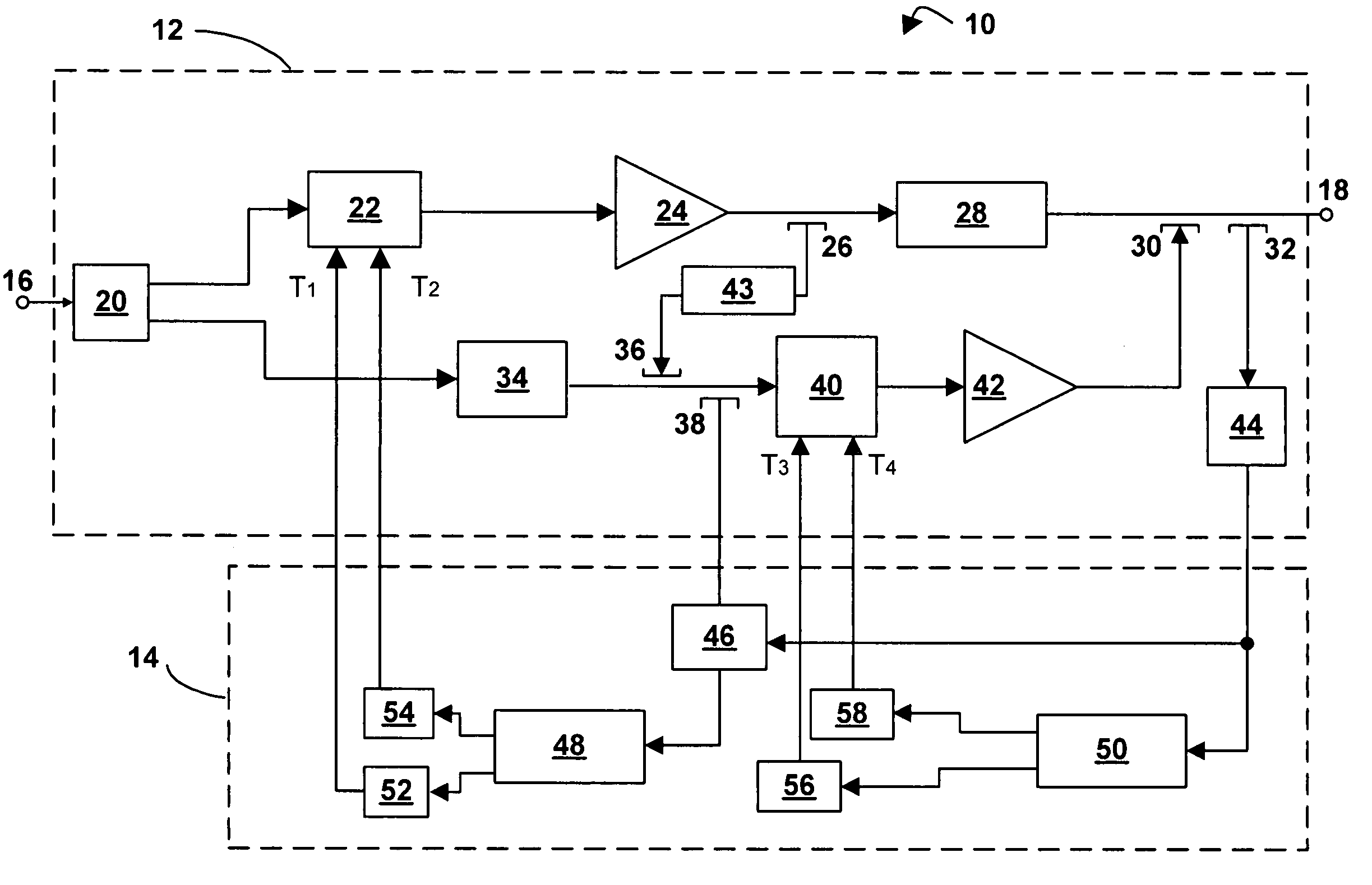
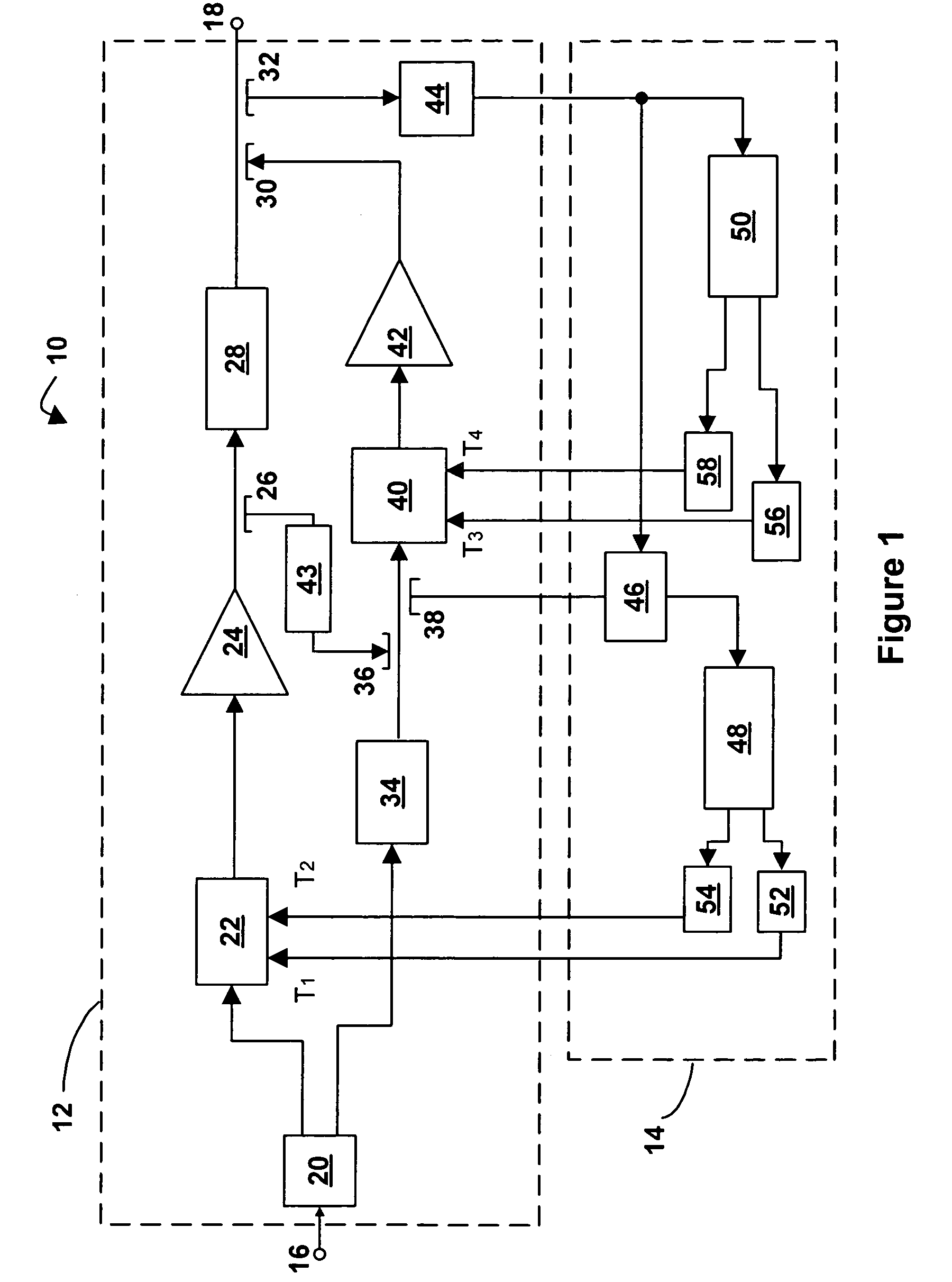
[0020]Referring now to FIG. 1, a feed-forward amplifier in accordance with an embodiment of the invention is indicated generally by reference numeral 10. The feed-forward amplifier 10 comprises an amplifier portion 12 and a detector-controller portion 14.

[0021]The amplifier portion 12 has an input port 16 and an output port 18. A main signal path runs between the input port 16 and the output port 18 and consists of a series connection of a first main path splitter 20, a main signal path gain and phase adjuster 22, a main amplifier 24, a second main path splitter 26, a main signal path delay element 28, a first main path coupler 30, and a third main path splitter 32.

[0022]While one output of first main path splitter 20 continues along the main signal path, the other output of first main path splitter 20 heads along a feed-forward path consisting of a feed-forward signal path delay element 34, a feed-forward path coupler 36, a feed-forward path splitter 38, a feed-forward signal path ...


PUM


Abstract

An apparatus and method for operating a feed-forward amplifier in which, after the signal-cancellation and intermodulation-cancellation loops have initially been nulled, the feed-forward amplifier is operated so that both loops are controlled so as to minimize intermodulation at the output of the feed-forward amplifier.

Description

[0001]This application is a 371 of PCT / US03 / 19849, filed Jun. 25, 2003, which claims priority to US Provisional Application No. 60 / 391,084, filed Jun. 25, 2002, the entire contents of which is incorporated by reference herein.FIELD OF THE INVENTION[0002]The present invention relates to feed-forward amplifiers. More specifically, the present invention relates to an apparatus and method for controlling gain and phase adjustments in a feed-forward amplifier.BACKGROUND OF THE INVENTION[0003]One well-known form of amplifier is the feed-forward amplifier. In order to achieve linearity in a feed-forward amplifier, careful control of the amplifier circuitry is required. In particular, in feed-forward amplifiers two or more gain and phase adjusters are often employed and the taps of each of these adjusters are carefully steered to achieve linearity through the amplifier.[0004]Within the art of feed-forward amplifiers, it is known to use detector-controller circuits, one for each gain-and-pha...

Claims


Application Information

Patent Timeline
Patent Type & Authority Patents(United States)
IPC IPC(8): H03F1/32H03F1/26
CPCH03F1/3229
Inventor BLODGETT, JAMES R.
Owner WI LAN INC
Why Eureka
Try Eureka