In-Ceiling Focus Located Surgical Lighting

Inactive Publication Date: 2008-08-14
OPTIMUS SERVICES
View PDF7 Cites 12 Cited by
  • Summary
  • Abstract
  • Description
  • Claims
  • Application Information

AI Technical Summary

Benefits of technology

[0026]In keeping with the present invention, it is an object of the invention to provide rapid, on-the-fly tracking of a surgical site or other site to be illuminated.
[0027]As such, the present invention discloses the use of a wireless radio-frequency transmitter, such as a Bluetooth transmitter, which is adapted to transmit a distance signal to a receiver. The receiver then provides adjustment by way of an actuator of a single light source or an array of light sources, thereby providing an illuminating field with the further advantage that the latter array design will minimize shadows. In addition, the transmitter, in one embodiment, is of a small profile and constructed in biocompatible materials. The device may be either sterilizable for reuse or disposable, thereby allowing packing of the transmitter in a sterile container and further allowing placement of the device in, on, or by a surgical site.
[0028]It is another object of the invention to provide an illumination field that provides maximal shadow cancellation while also providing an intense, focused illumination field.
[0029]Light sources congregated about a single point, such as in a circle, allow the individual light sources to be targeted at a particular point. As the radius between any individual light source and the center of the circle decreases, the ability of the light sources to work to cancel shadows decreases. When the radius approaches zero, the resultant array of lights is equivalent to a single beam. As such, the pres

Problems solved by technology

Unfortunately, as the distance between a light source and a target source i

Method used


Image

  • In-Ceiling Focus Located Surgical Lighting
  • In-Ceiling Focus Located Surgical Lighting
  • In-Ceiling Focus Located Surgical Lighting

Examples


Embodiment Construction

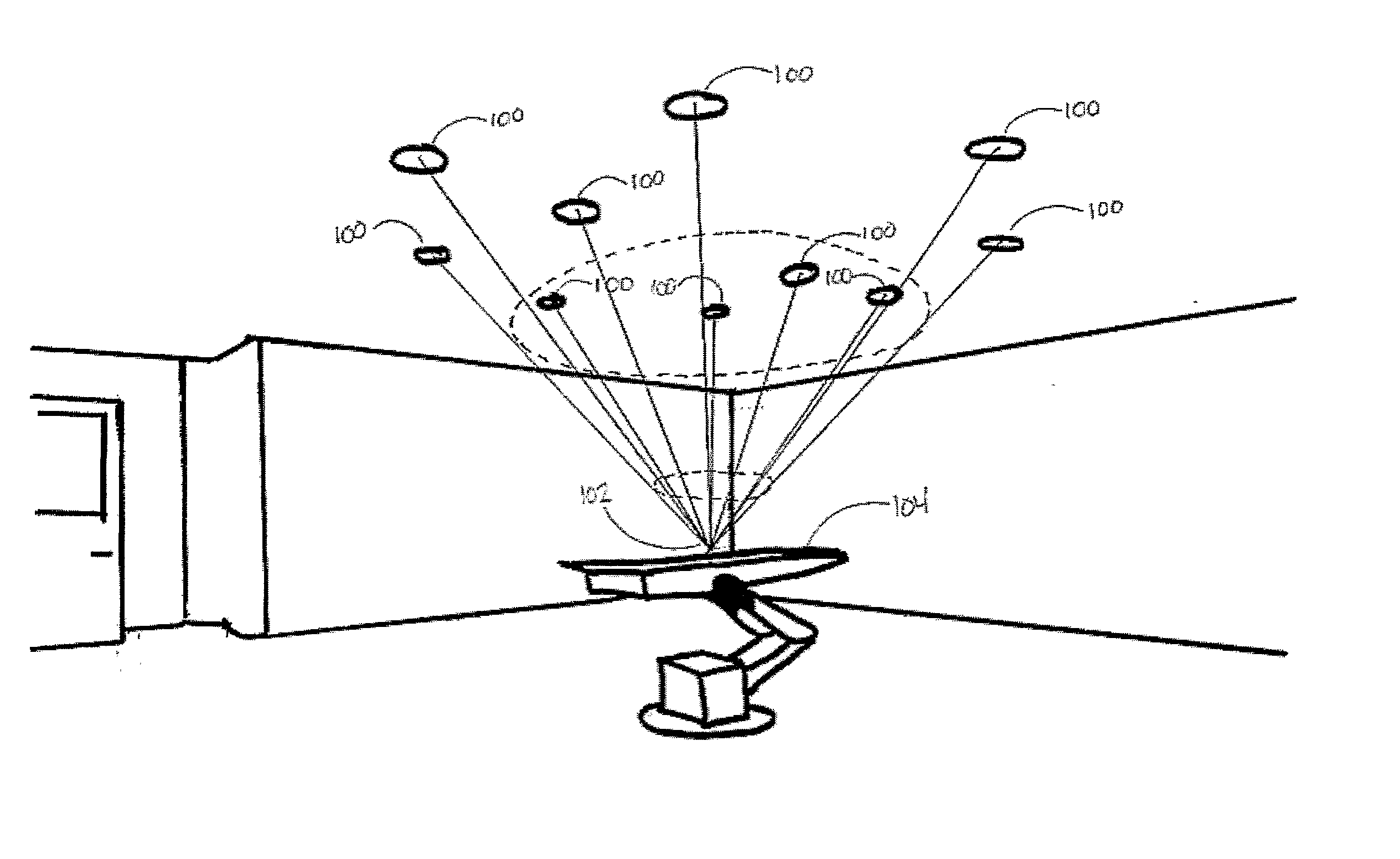
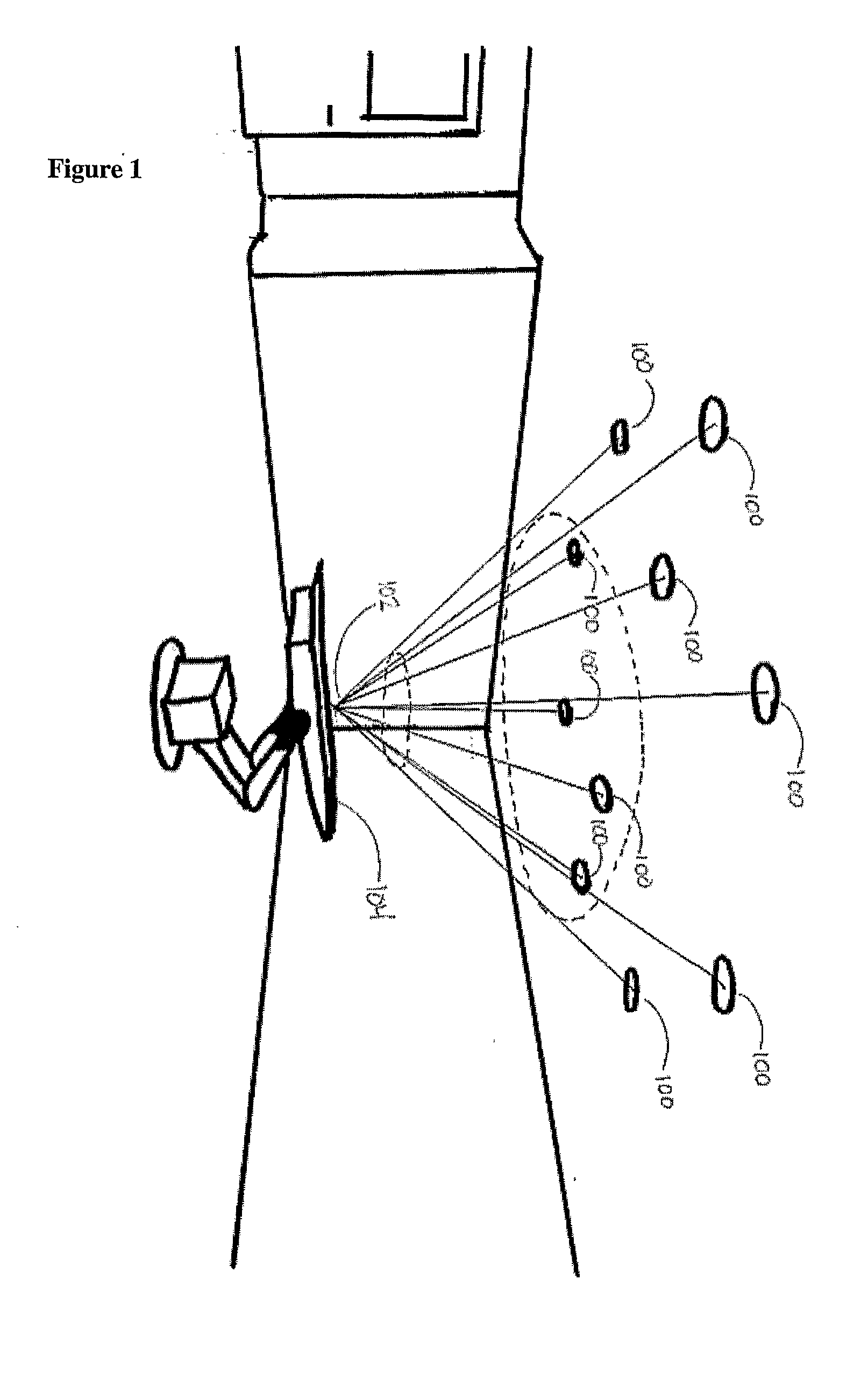
[0040]With respect to the drawings, FIG. 1 shows a typical surgical operating room with one possible arrangement of lights 100 positioned in accord with present invention. The dotted circles and lines intersecting through them to a point 102 on surgical table 104 indicates the diminishing illuminating field of the focused lights 100. Since the lights 100 are spaced distant from each other, they are thereby adapted to provide additional lines-of-sight to a target area such as point 102.

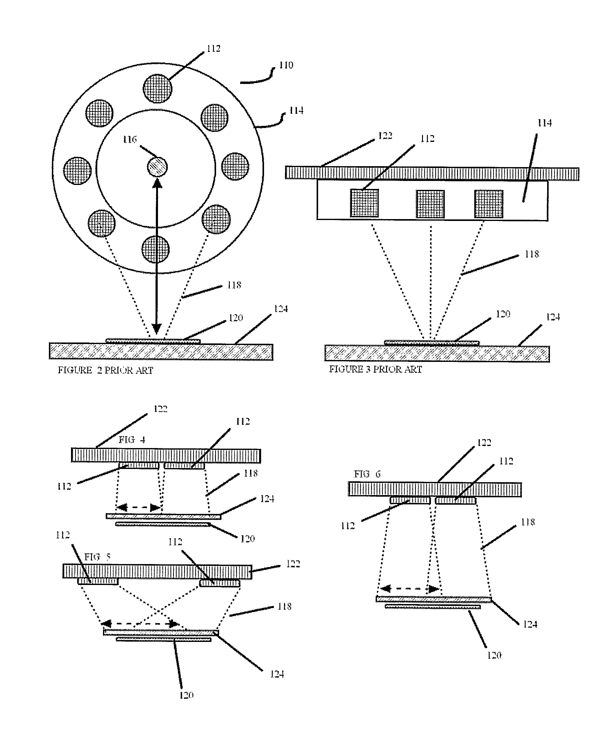
[0041]In contrast, in a typical example of the prior art, shown in FIGS. 2 and 3, auto-adjustable surgical lights 112 arrayed in a single housing 114 provide an illuminating light 118 toward illumination target 120 on table 124. The illumination target 120 is located by a device 116 which may be an ultrasonic detector. As FIG. 3 demonstrates, the prior art includes light housings 114 that are attached to a ceiling 122, thereby consuming overhead working space.

[0042]FIGS. 4, 5, and 6 demonstrate some of...


PUM


Abstract

An invention that provides improved means for automatic illumination of a surgical site is disclosed. By way of utilizing a wireless radio-frequency transmitter adapted to transmit a distance signal to a receiver, which provides adjustment, by way of an actuator, of a single light source or an array of light sources, an illuminating field is provided with the further advantage that shadows are minimized. In addition, the transmitter, in one embodiment, is of a small profile and constructed in biocompatible materials. The device may be either sterilizable for reuse or disposable, thereby allowing packing of the transmitter in a sterile container thereby further allowing placement of the device in, on, or by a surgical site. The present invention also discloses an array of lights that are arrayed more distant from each other than typical and yet provides a focused, intense illumination field with maximal line of sight approach owing to the discrete (recessed) housing of the light sources. Lastly, the recessed housing allows more efficient use of overhead working space.

Description

CROSS-REFERENCE TO RELATED APPLICATIONS[0001]This application claims the benefit of provisional patent application U.S. Ser. No. 60 / 701,106, filed Jul. 20, 2005 by the present inventor. The contents of U.S. Ser No. 60 / 701,106 are expressly incorporated herein by reference thereto.[0002]The following references are hereby explicitly incorporated by reference thereto:[0003]U.S. Pat. No. 4,025,777 (to which German Patent 25 19 426 corresponds)[0004]U.S. Pat. No. 4,639,838[0005]U.S. Pat. No. 4,884,008[0006]U.S. Pat. No. 4,887,196[0007]U.S. Pat. No. 5,347,431[0008]U.S. Pat. No. 5,584,568[0009]German Patent Disclosure Document DE-OS 32 27 494[0010]Applications filed along with present application by current inventor on this date entitled:[0011]HOSPITAL OPERATING ROOM RE-DESIGN[0012]AMBIENT LIGHTING IN HOSPITAL SURGICAL ENVIRONMENTS[0013]USE OF ULTRAVIOLET GERMICIDAL IRRADIATION IN HEALTH CARE ENVIRONMENTS[0014]IN-WALL WASTE RECEPTACLES FOR HOSPITAL AND LABORATORY ENVIRONMENTS[0015]MULTIFU...

Claims


Application Information

Patent Timeline
IPC IPC(8): F21S8/02F21Y101/00
CPCA47L11/302H05B37/0272A47L2201/00A61B19/0287A61B19/0288A61B2019/0202A61B2019/025A61B2019/0267B01L1/50B65F1/0093B65F1/06E04B5/48H01R13/005H01R27/02A61B19/5202A61B2019/5251A47L11/40A61B2050/314A61B90/30A61B2050/005A61B50/13A61B50/36A61B50/362A61B2034/2051H05B47/19Y02B20/40A61B90/35
Inventor MANGIARDI, JOHN R.
Owner OPTIMUS SERVICES
Why Eureka
Try Eureka