Method and apparatus for avoiding pattern blockage due to scatter

a scattering and pattern technology, applied in the direction of electrical equipment, antennas, antenna couplings, etc., can solve the problems of inability to locate antennas on airborne platforms, inability to place materials of appropriate thickness and orientation on objects, and inability to add extra antennas to cover these poorly illuminated areas. , to achieve the effect of minimizing the shadow caused by the structure, less deformation, and more delay

Inactive Publication Date: 2014-07-29
BAE SYST INFORMATION & ELECTRONICS SYST INTEGRATION INC
View PDF3 Cites 0 Cited by
  • Summary
  • Abstract
  • Description
  • Claims
  • Application Information

AI Technical Summary

Benefits of technology

[0013]This alteration can either flatten the phase of the wave front that impinges on the obstacle, or can alter the phase of a signal reflected by the obstacle to minimize nulls in the antenna pattern. When the artificial surface is used to flatten the phase of the radially expanding signal in front of the obstacle so as to present a plane wave front to the obstacle, the far field is filled in behind the obstacle, thus to minimize the shadow. By re-curving the wave front to be flat, the field illuminating the obstacle would have the appearance of a plane wave whose “effective aperture” is larger than the blockage aperture of the obstacle. This in turn would force more signal in the direction of the shadow, thus minimizing its darkness.
[0014]The second effect of the artificial surface is to provide that the energy that is collected and reradiated by the artificial surface impinges on the obstacle such that the energy reflected by an electrically conductive obstacle has phase that does not cancel energy from the antenna radiating away from the obstacle. By controlling the phase of the incident field on the obstruction before it is reflected, the phase of the backward reflecting signal can be made to add to or enhance the antenna radiation pattern in the opposite direction instead of creating nulls. In short, energy reflected from the obstacle is made to constructively add to the energy direct from the antenna.
[0020]On the other hand, the low profile light meanderline structures can capture enough energy and can be used to fill the void cast by the obstacles shadow either by changing the spherical wave to a plane wave or by making sure that the reflected energy has an appropriate constructive addition phase.
[0021]The variable impedance transmission line in one embodiment includes multiple strip line sections of high and low impedance transmission line sections. The low impedance sections are closer to the ground plane and can be further loaded with varactors or other tunable capacitive components. The high impedance sections are those which are higher above the ground plane. Because of the height above the ground plane, these strip lines have high fringing fields which radiate or leak to free space. The fields in the lower impendence sections have much less fringing and thereby preventing leakage.
[0025]Note in one embodiment the array of meanderlines is tapered in size, namely in length, to provide more delay directly in front of the antenna and less to the sides. In this manner it is possible to reshape the spherical wave front as it travels down the meanderline and to make its reradiation wavefront appear to be that of a plane wave.
[0027]The advantage of the meanderline or VITL construction is that the artificial surface may be constructed of lightweight foam or honeycomb material over a thin fiber glass substrate bonded to the ground plane in front of the obstacle. The entire structure can be enclosed in a lightweight radome material to form a composite structure. Note, the tuning of the meanderlines in effect is accomplished through the low impedances associated with the inner meanderline sections, whereby the delay can be controlled by electro-active actuators or varactor controlled capacitances, thus to be able to tune the meanderlines or VITLs to any specific operating frequency. The ability to tune the meanderlines means that the required phase of the collected and reradiated signal can be achieved through appropriate meanderline structures tuned to the operating frequency. Also, the ability to tune the meanderline array structure provides that the wave which finally impinges on the obstruction does in fact have a flat wave front, whereby it is less defracted by the structure, thus minimizing the shadow caused by the structure.

Problems solved by technology

It is noted that it is nearly impossible to locate antennas on airborne platforms that have a perfect 360° field of view.
Adding extra antennas to cover these poorly illuminated areas is usually not an option due to the added weight of the antenna and cabling, as well as switching accessories, air drag, added cosite interference problems or simply the lack of room for another antenna.
For complex obstacle shapes, placing of materials of appropriate thickness and orientation on the object is impractical.
An additional problem with close obstructions is that they can reflect strong signals back to the antenna and beyond.

Method used


Image

  • Method and apparatus for avoiding pattern blockage due to scatter
  • Method and apparatus for avoiding pattern blockage due to scatter
  • Method and apparatus for avoiding pattern blockage due to scatter

Examples


Embodiment Construction

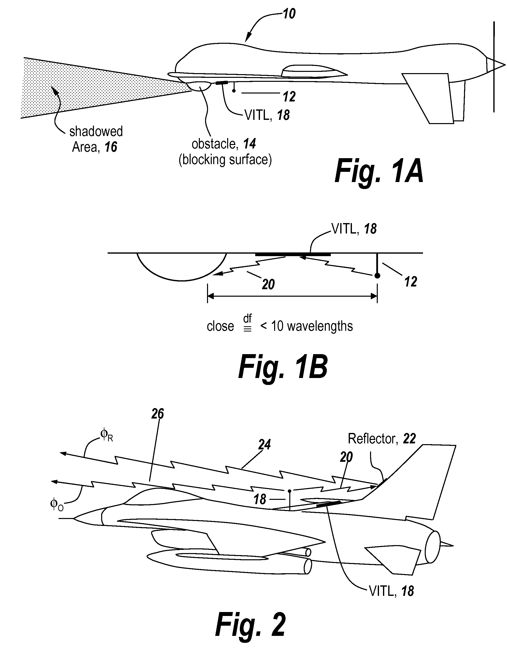
[0041]Referring now to FIG. 1A, an aircraft 10 may be provided with an antenna 12 which is closely spaced to an obstacle 14 that constitutes a blocking surface such that radiation from antenna 12 is blocked by obstacle 14 to provide a shadowed area 16 in the far field. As will be discussed, an artificial surface in the form of a meanderline or VITL 18 is interposed between antenna 12 and obstacle 14, the purpose of which is to alter the phase of the energy that travels down the meanderline and towards the obstacle. As will be described it is the purpose of the meanderline or VITL 18 to alter the phase of the signal which is captured and reradiated towards the obstacle.

[0042]It will be noted that the meanderline or VITL is a slow wave structure which in one embodiment is an array of meanderlines.

[0043]The blocking situation depicted in FIG. 1A is depicted in FIG. 1B and is a result of the antenna being close to the obstruction, for instance less than 10 wavelengths. Of course the clo...


PUM


Abstract

A method and apparatus is provided for avoiding pattern blockage due to scatter from an object in which an artificial surface directs the energy from the antenna prior to arriving at a blocking structure such that either the wave fronts of the energy are linear when they arrive at the blocking structure or the phase of the energy incident on the object is adjusted such that the energy reflected from the object is in phase with energy directly from the antenna radiating elsewhere in the far field pattern, or both.

Description

FIELD OF THE INVENTION[0001]This invention relates to mitigation of pattern blockage and pattern nulls due to the scattering of RF energy from an object near an antenna and more particularly to the use of an artificial surface which collects and reradiates energy from the antenna prior to arriving at the blocking structure such that the wave fronts of the energy are linear when they arrive at the blocking structure and such that the reflected energy from the blocking structure is adjusted.BACKGROUND OF THE INVENTION[0002]It is noted that it is nearly impossible to locate antennas on airborne platforms that have a perfect 360° field of view. Usually there is a close obstruction or scatterer in a particular direction that prevents the antenna from seeing around it. A shadow related to the blockage width is cast upon the pattern of the antenna along the direction of the obstruction. The result is a shadow area to the far side of the obstruction that blocks passage of RF energy, thus pr...

Claims


Application Information

Patent Timeline
Patent Type & Authority Patents(United States)
IPC IPC(8): H01Q15/04H01Q1/52H01Q3/44H01Q15/00H01Q15/06
CPCH01Q15/0066H01Q15/002H01Q1/52H01Q3/443H01Q15/242
Inventor APOSTOLOS, JOHN T.CHARETTE, DAVID P.GILBERT, ROLAND A.
Owner BAE SYST INFORMATION & ELECTRONICS SYST INTEGRATION INC
Why Eureka
Try Eureka