Framing system for use with silicone edge graphics

a technology of silicone edge and frame, which is applied in the direction of illuminated signs, signs, display means, etc., can solve the problems of increasing the overall cost of using the seg frame and remaining challenges, and achieve the effect of minimizing the shadow

Pending Publication Date: 2021-08-12
DESIGN TO PRINT INC
View PDF21 Cites 0 Cited by
  • Summary
  • Abstract
  • Description
  • Claims
  • Application Information

AI Technical Summary

Benefits of technology

[0010]Various embodiments of the present invention provide mounting systems comprising a plurality of framing pieces assembled to provide a desired mounting surface. In some instances, the present invention provides a mounting system comprising a plurality of identical framing pieces. In some instances, the present invention provides a mounting system comprising a plurality of unique framing pieces. In some embodiments, at least four identical types or embodiments of framing members are attached at corresponding ends to provide a rectangular frame having a height and a width defining an area for receiving a SEG product. In some embodiments, the framing members are attached at respective ends using an attachment means, such as, for example a metal tenon or bar configured to insert within corresponding tracks or slots of the framing members, such as a t-track slot, wherein the attachment means is secured by a mechanical fastener, such as a set screw. In some instances, the attachment means is a linear metal tenon, bar or joint bracket fastener. In some instances, the attachment means is an elbow or right-angle metal tenon, bar or joint bracket fastener. In some instances, the attachment means is a t-shaped metal tenon, bar or joint bracket fastener. In some instances, the attachment means is an x-shaped metal tenon, bar or joint bracket fastener. Some framing members include a threaded channel configured to receive a threaded bolt at any location along a length of the threaded channel.
[0011]In a first aspect of the invention, a framing member is provided comprising a base having an outer surface, an inner surface, a distal end, and a front receptacle formed in the distal end and configured to receive a silicone bead of a SEG product, said inner surface comprising a chamfered surface in proximity to the front receptacle and tapered inwardly towards an opening of the front receptacle, the framing member further comprising a surface in proximity to the chamfered surface and configured to receive a light source. In some implementations of the invention, the inner surface of the base comprises the surface configured to receive a light source. In some implementations of the invention, the inner surface further comprises a second front receptacle positioned inwardly from the front receptacle and configured to receive a silicone bead of a second SEG product, the inner surface comprising a second chamfered surface in proximity to the second front receptacle and tapering outwardly towards the second front receptacle. In some implementations of the invention, the chamfered surface is configured to minimize a shadow on a SEG product mounted in the front receptacle when the framing member is used with a light source. In some instances, the framing member further includes a threaded channel in the outer surface of the base. In some implementations of the invention, the base comprises a proximal end opposite the distal end, said proximal end comprising a rear receptacle configured to receive a silicone bead of a second SEG product, wherein the second chamfered surface is configured to minimize a shadow on a second SEG product mounted in the rear receptacle when the framing member is used with a light source. In some instances, the framing member comprises a vertical member extending outwardly from and perpendicular to the base and comprising a second chamfered surface opposite the base and tapered outwardly from the base. In some instances, a vertical member of the framing member comprises a second surface receiving a light source, the second surface positioned between the base and the second chamfered surface, the second chamfered surface tapered away from the second surface. In some instances, the second surface is perpendicular to the base. In some instances, the second surface is parallel to the base. In some instances, the second surface comprises a channel. In some instances, the second surface comprises a raised edge opposite the second chamfered surface and between the second surface and the front receptacle, a portion of the raised edge being perpendicular to the base.

Problems solved by technology

These modifications require skill, training, specialized tools and cutting guides, as well as valuable time in order to achieve professional results, all of which increase the overall costs associated with using the SEG frame.
Thus, while framing systems and methods exist for mounting and displaying SEG products, challenges remain.

Method used


Image

  • Framing system for use with silicone edge graphics
  • Framing system for use with silicone edge graphics
  • Framing system for use with silicone edge graphics

Examples


Embodiment Construction

[0043]The presently preferred embodiments of the present invention will be best understood by reference to the drawings, wherein like reference numbers indicate identical or functionally similar elements. It will be readily understood that the components of the present invention, as generally described and illustrated in the figures herein, could be arranged and designed in a wide variety of different configurations. Thus, the following more detailed description, as represented in the figures, is not intended to limit the scope of the invention as claimed, but is merely representative of presently preferred embodiments of the invention.

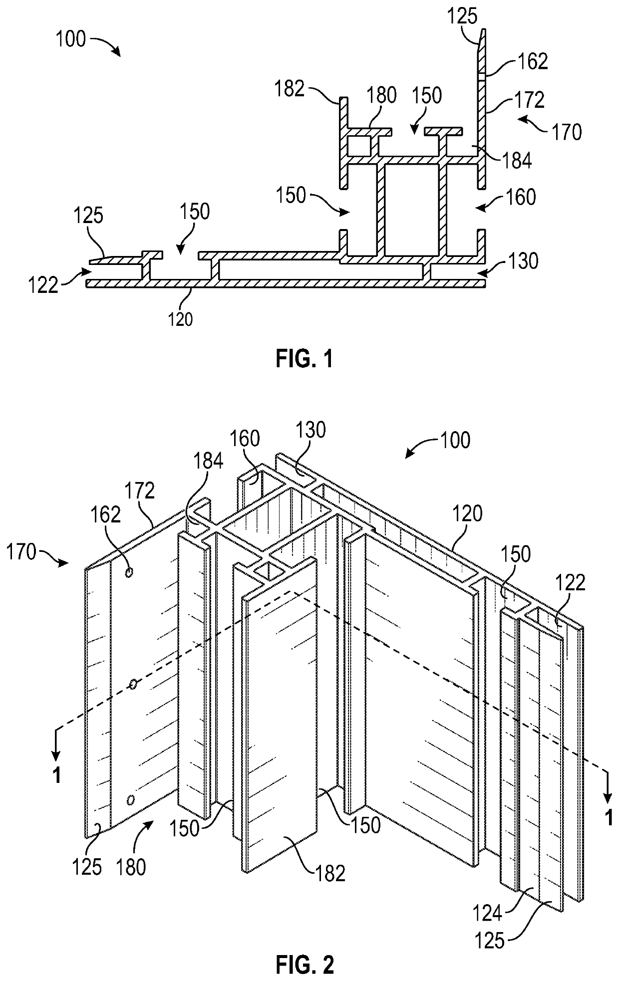
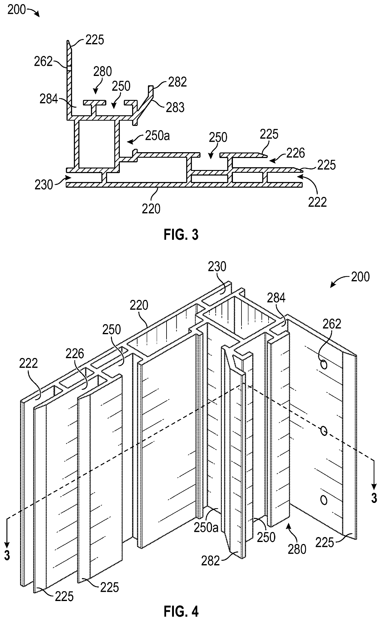
[0044]Referring now to FIGS. 1-4, various framing members (100, 200) are shown having features for mounting and displaying a SEG product. In some embodiments, framing members 100 and 200 comprise an L-shape having first and second arms in perpendicular orientation. Framing members 100 comprise a first arm 120 forming a base and having a front receptac...


PUM


Abstract

Framing member for use in mounting and displaying a SEG product.

Description

RELATED APPLICATIONS[0001]This application claims priority to U.S. Provisional Patent Application Ser. No. 62 / 972,356 filed Feb. 10, 2020, which is incorporated herein by reference in its entirety.BACKGROUND OF THE INVENTION[0002]Silicone edge graphics (SEG) is a fabric material having a thin silicone strip (or welt / gasket) sewn or otherwise attached to the perimeter thereof. The thin silicone strip is used as an anchor to attach the SEG to a frame (a SEG frame) such that a viewable surface of the fabric material is displayed for viewing. In some instances, the viewable surface of the fabric material comprises a printed image. A SEG frame may include various features to accommodate a preferred orientation or presentation of the viewable surface. In some instances, a SEG frame includes features to accommodate flush mounting, standalone mounting, and / or hang mounting, as well as features to provide backlighting of the viewable surface.[0003]A SEG frame generally comprises a plurality ...

Claims


Application Information

Patent Timeline
Patent Type & Authority Applications(United States)
IPC IPC(8): G09F7/18G09F13/18
CPCG09F7/18G09F2013/1881G09F2007/1843G09F13/18
Inventor BEVANS, JOSHSTODDARD, HOWARDROMNEY, JACOB
Owner DESIGN TO PRINT INC
Why Eureka
Try Eureka