Multilayer capacitor

a multi-layer capacitor and capacitor technology, applied in the field of multi-layer capacitors, to achieve the effect of enhancing the capacitance, increasing the equivalent series resistance, and reducing the resistance of the series

Active Publication Date: 2008-05-06
TDK CORPARATION
View PDF7 Cites 12 Cited by
  • Summary
  • Abstract
  • Description
  • Claims
  • Application Information

AI Technical Summary

Benefits of technology

[0008]For overcoming the problem mentioned above, it is an object of the present invention to provide a multilayer capacitor which can increase the equivalent series resistance.
[0024]The present invention can provide a multilayer capacitor which can increase the equivalent series resistance.

Problems solved by technology

However, the multilayer capacitor disclosed in Patent Document 1 is silent on how to increase the equivalent series resistance.

Method used


Image

  • Multilayer capacitor
  • Multilayer capacitor
  • Multilayer capacitor

Examples


first embodiment

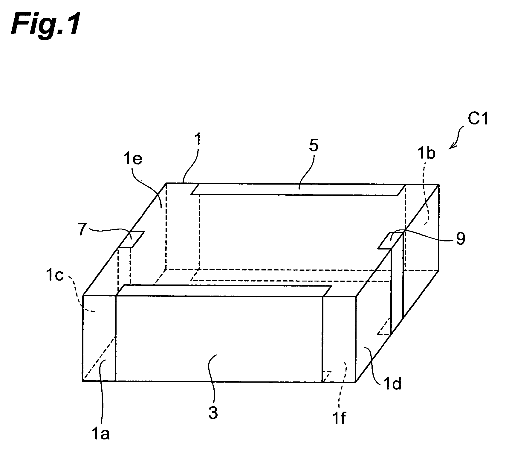
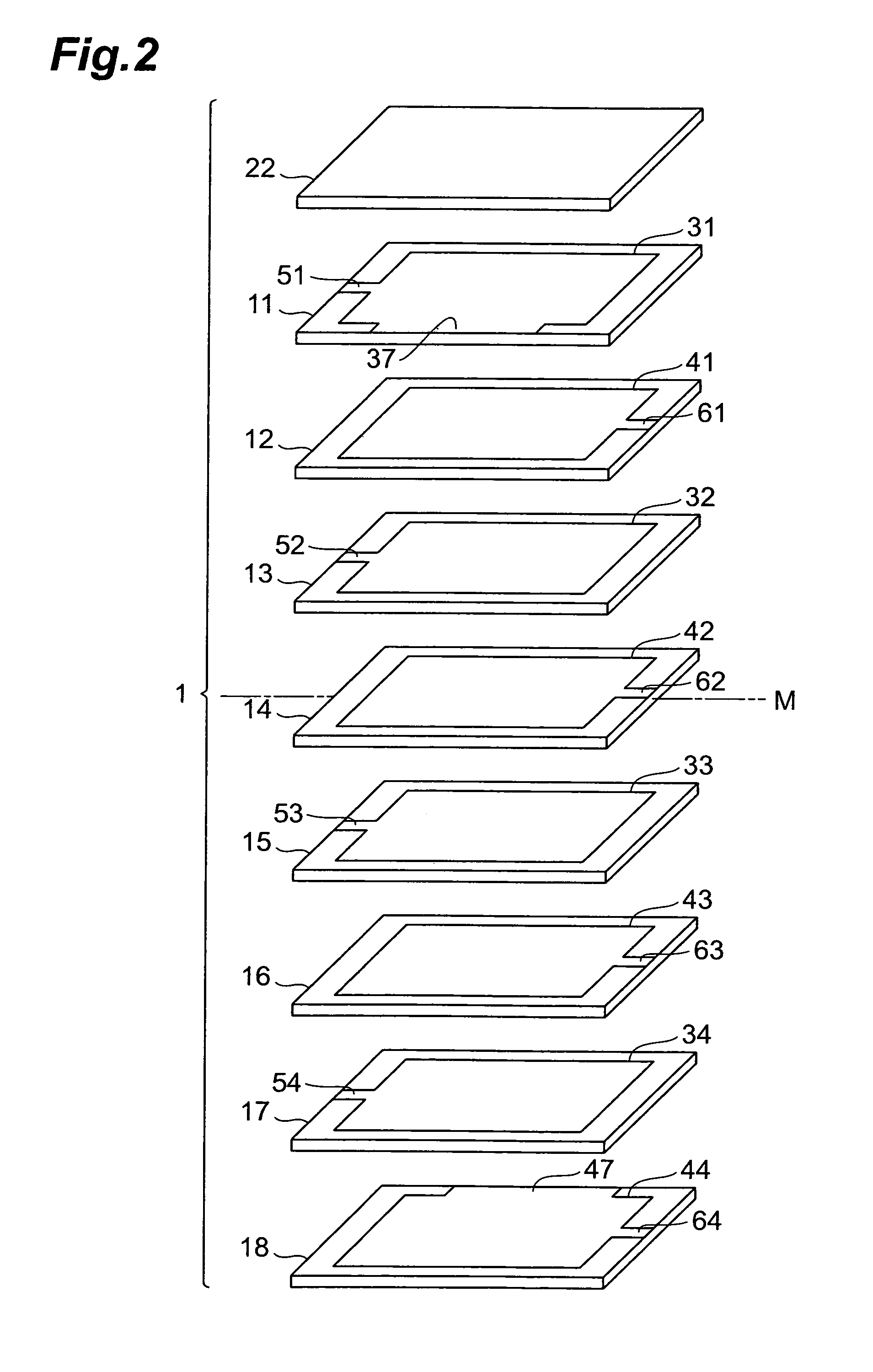
[0053]With reference to FIGS. 1 and 2, the structure of the multilayer capacitor C1 in accordance with a first embodiment will be explained. FIG. 1 is a perspective view of the multilayer capacitor in accordance with the first embodiment. FIG. 2 is an exploded perspective view of the multilayer body included in the multilayer capacitor in accordance with the first embodiment.

[0054]As shown in FIG. 1, the multilayer capacitor C1 comprises a multilayer body 1, first and second terminal electrodes 3, 5 formed on the multilayer body 1, and first and second connecting conductors 7, 9.

[0055]The first terminal electrode 3 is formed on a side face 1a extending longitudinally in side faces parallel to a laminating direction which will be explained later in the multilayer body 1. The second terminal electrode 5 is formed on a side face 1b extending longitudinally and opposing the side face 1a formed with the first terminal electrode 3 in the side faces parallel to the laminating direction to ...

second embodiment

[0074]With reference to FIG. 5, the structure of the multilayer capacitor in accordance with a second embodiment will be explained. The multilayer capacitor in accordance with the second embodiment differs from the multilayer capacitor C1 in accordance with the first embodiment in terms of positions of a first inner electrode 33 connected to a first terminal electrode 3 through a lead conductor 37 and a second inner electrode 42 connected to 1a second terminal electrode 5 through a lead conductor 47 in the laminating direction. FIG. 5 is an exploded perspective view of the multilayer body included in the multilayer capacitor in accordance with the second embodiment.

[0075]As with the multilayer capacitor C1 in accordance with the first embodiment, the multilayer capacitor in accordance with the second embodiment comprises a multilayer body 1, the first terminal electrode 3 formed on the multilayer body 1, the second terminal electrode 5 similarly formed on the multilayer body 1, and ...

third embodiment

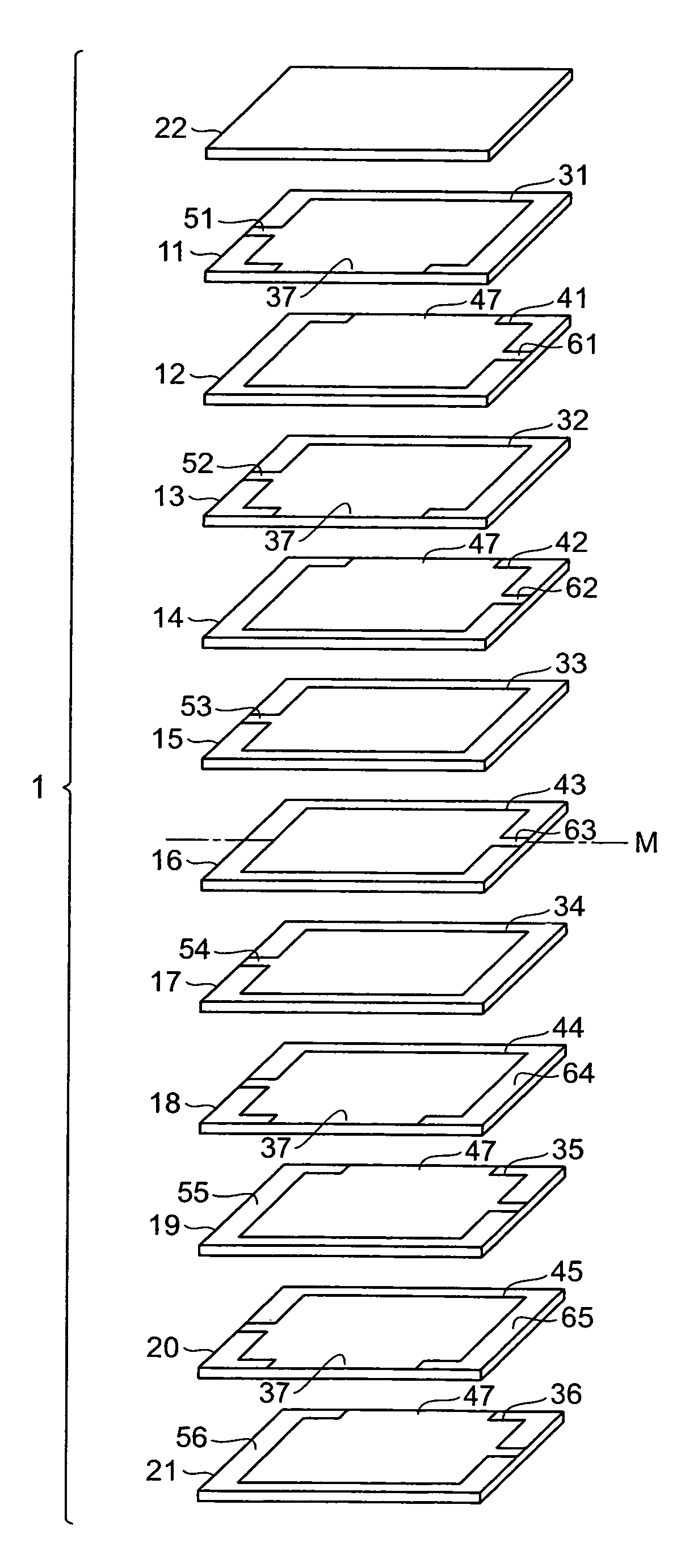
[0084]With reference to FIG. 6, the structure of the multilayer capacitor in accordance with a third embodiment will be explained. The multilayer capacitor in accordance with the third embodiment differs from the multilayer capacitor C1 in accordance with the first embodiment in terms of the number of first and second inner electrodes 31, 34, 41, 44 connected to terminal electrodes 3, 5 through lead conductors 37, 47. FIG. 6 is an exploded perspective view of the multilayer body included in the multilayer capacitor in accordance with the third embodiment.

[0085]As with the multilayer capacitor C1 in accordance with the first embodiment, the multilayer capacitor in accordance with the third embodiment comprises a multilayer body 1, the first terminal electrode 3 formed on the multilayer body 1, the second terminal electrode 5 similarly formed on the multilayer body 1, and first and second connecting conductors 7, 9, which are not depicted.

[0086]In the multilayer capacitor in accordanc...


PUM


Abstract

The multilayer body 1 is constructed by alternately laminating a plurality of dielectric layers 11 to 22 and a plurality of first and second inner electrodes 31 to 34, 31 to 34. The first inner electrodes 31 to 34 are electrically connected to each other through the first connecting conductor 7. The first inner electrode 31 is electrically connected to the first terminal electrode 3 through the lead conductor 37. The second inner electrodes 41 to 44 are electrically connected to each other through the second connecting conductor 9. The second inner electrode 44 is electrically connected to the second terminal electrode 5 through the lead conductor 47. The first inner electrode 31 and the second inner electrode 44 are arranged at respective positions symmetrical to each other about the center position M in the laminating direction of the multilayer body 1.

Description

BACKGROUND OF THE INVENTION[0001]1. Field of the Invention[0002]The present invention relates to a multilayer capacitor.[0003]2. Related Background Art[0004]Known as this kind of multilayer capacitor is one comprising a multilayer body in which a plurality of dielectric layers and a plurality of inner electrodes are alternately laminated, and a plurality of terminal electrodes formed on the multilayer body (see, for example, Patent Document 1).[0005]Power supplies for central processing units (CPUs) mounted in digital electronic devices have been lowering their voltage but increasing their load current. This has made it very difficult to suppress fluctuations of power voltage within a tolerable range in response to drastic changes in load current. Therefore, a multilayer capacitor known as decoupling capacitor has come into connection with power supplies. This multilayer capacitor supplies a current to a CPU at the time when the load current transiently fluctuates, so as to restrain...

Claims


Application Information

Patent Timeline
Patent Type & Authority Patents(United States)
IPC IPC(8): H01G4/005H01G4/06
CPCH01G4/232H01G4/30H01G4/33H01G4/255
Inventor TOGASHI, MASAAKI
Owner TDK CORPARATION
Why Eureka
Try Eureka