Multilayer capacitor

a multi-layer capacitor and capacitor technology, applied in the field of multi-layer capacitors, can solve the problems of difficult control of equivalent series resistance, the demand for increasing the capacity of multi-layer capacitors and the demand for increasing equivalent series resistance, and achieve the effect of easy regulation of equivalent series resistance and high precision

Active Publication Date: 2008-09-23
TDK CORPARATION
View PDF9 Cites 11 Cited by
  • Summary
  • Abstract
  • Description
  • Claims
  • Application Information

AI Technical Summary

Benefits of technology

[0008]For overcoming the above-mentioned problem, it is an object of the present invention to provide a multilayer capacitor which can regulate the equivalent series resistance easily with a high precision.
[0010]Therefore, the inventors diligently conducted studies about multilayer capacitors which can satisfy both of the demands for increasing the capacity and equivalent series resistance. As a result, the inventors have found a new fact that, even when the number of laminated inner electrodes is the same, the equivalent series resistance can be adjusted to a desirable value if the inner electrodes are connected to outer connecting conductors formed on the surface of the multilayer body and inner connecting conductors laminated within the multilayer body while making it possible to change the number of inner connecting conductors connected to the terminal conductors. The inventors have also found a new fact that the equivalent series resistance can be adjusted to a desirable value if the inner electrodes are connected to outer connecting conductors formed on the surface of the multilayer body and inner connecting conductors laminated within the multilayer body while making it possible to change positions of inner connecting conductors in the laminating direction of the multilayer body. When the number of inner connecting conductors connected to the terminal conductors is made smaller than that of inner electrodes in particular, the adjustment can be made such as to increase the equivalent series resistance.
[0012]By adjusting the number of first inner connecting conductors and the number of second inner connecting conductors, the multilayer capacitor in accordance with this aspect of the present invention sets the equivalent series resistance to a desirable value, and thus can control the equivalent series resistance easily with a high precision.
[0014]By adjusting the position and shape of the first inner connecting conductor in the multilayer body in the laminating direction and the position of the second inner connecting conductor in the multilayer body in the laminating direction, the multilayer capacitor in accordance with this aspect of the present invention sets the equivalent series resistance to a desirable value, and thus can control the equivalent series resistance easily with a high precision.
[0019]The present invention can provide a multilayer capacitor which can regulate the equivalent series resistance easily with a high precision.

Problems solved by technology

However, the following problem exists when adjusting the multilayer capacitor equipped with a terminal conductor having a multilayer structure including an inner resistance layer to a desirable value.
Namely, for adjusting the equivalent series resistance to a desirable value in a multilayer capacitor equipped with a terminal conductor having a multilayer structure including an inner resistance layer, the thickness and material composition of the inner resistance layer included in the terminal conductor must be regulated while remaining independent of the capacitor's capacitance and ESL, which makes it very difficult to control the equivalent series resistance.
Thus, the demand for increasing the capacity of the multilayer capacitor and the demand for increasing the equivalent series resistance contradict each other.

Method used


Image

  • Multilayer capacitor
  • Multilayer capacitor
  • Multilayer capacitor

Examples


tenth embodiment

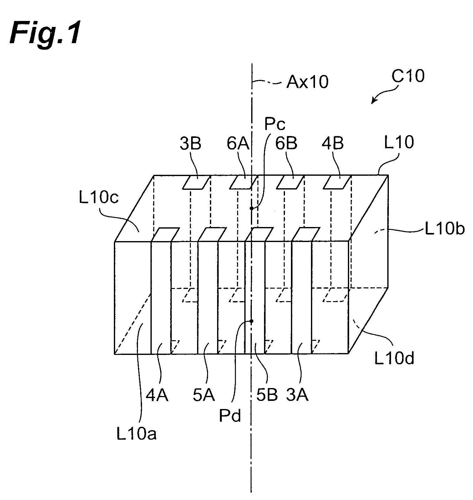
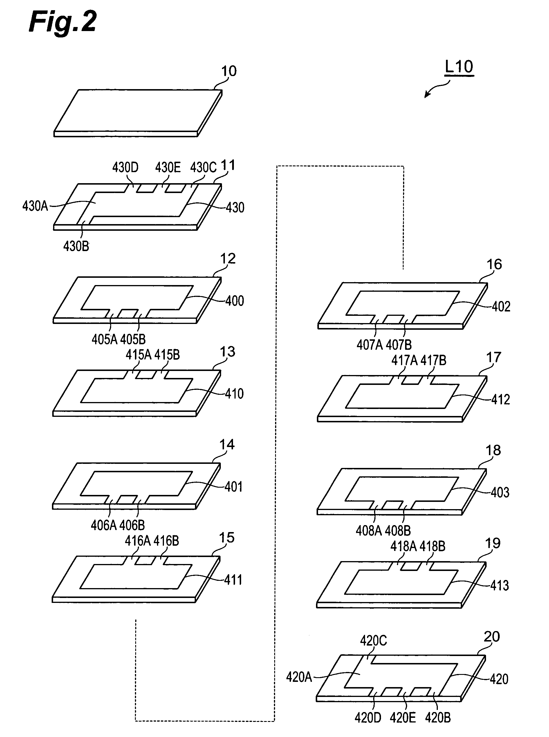
[0222]With reference to FIGS. 13 and 14, the structure of the multilayer capacitor C13 in accordance with a tenth embodiment will be explained. The multilayer capacitor C13 in accordance with the tenth embodiment differs from the multilayer capacitor C10 in accordance with the first embodiment in terms of arrangement of outer conductors formed on the multilayer body. FIG. 13 is a perspective view of the multilayer capacitor in accordance with the tenth embodiment. FIG. 14 is an exploded perspective view of the multilayer body included in the multilayer capacitor in accordance with the tenth embodiment.

[0223]On a first side face L13a which is a side face extending longitudinally of faces L13c and L13d orthogonal to the laminating direction of the multilayer body L13 among side faces parallel to the laminating direction of the multilayer body L13, a first terminal conductor 3A, a second outer connecting conductor 6A, a first outer connecting conductor 5A, and a second terminal conduct...

eleventh embodiment

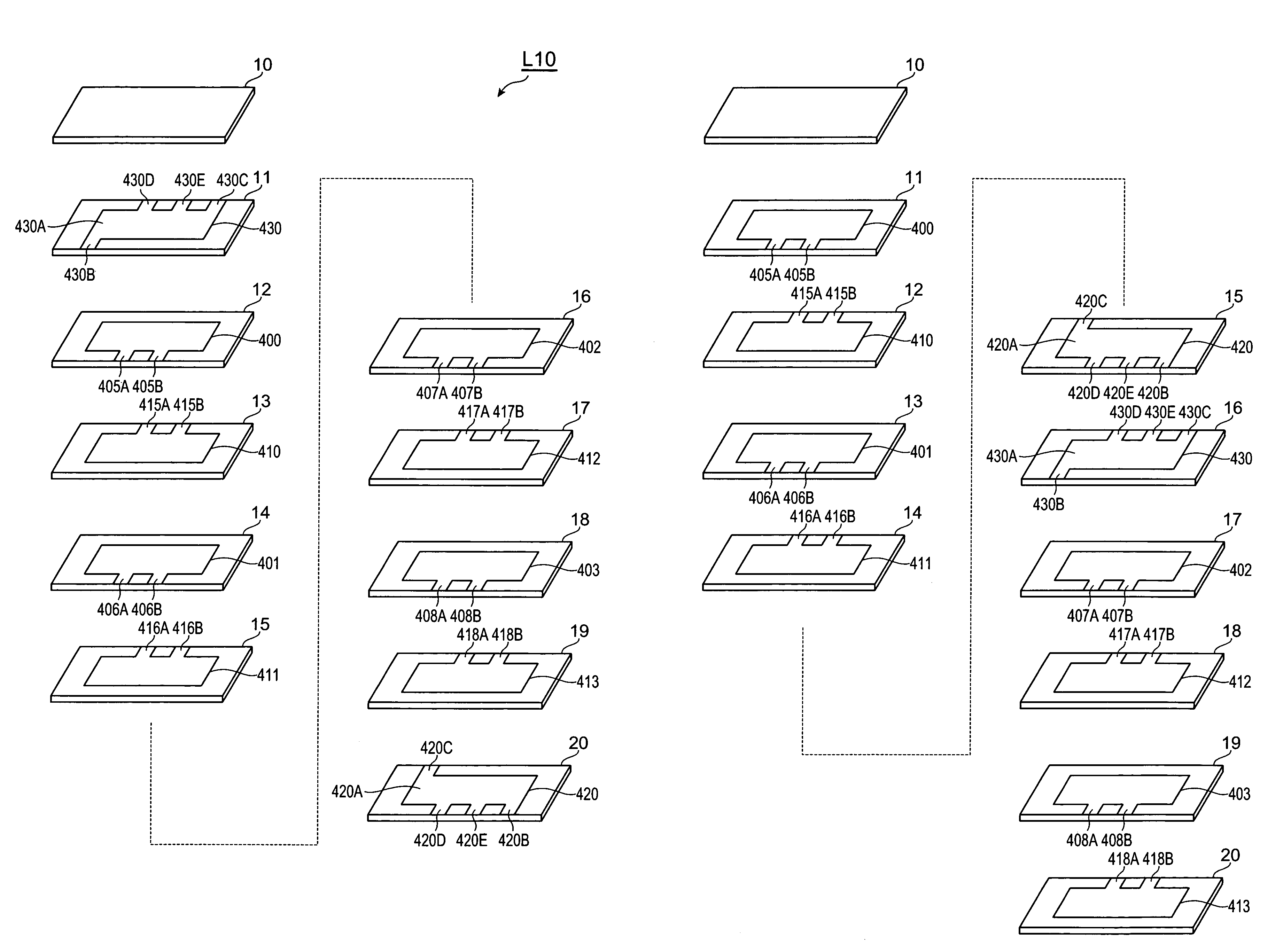
[0238]With reference to FIG. 15, the structure of the multilayer capacitor in accordance with an eleventh embodiment will be explained. The multilayer capacitor in accordance with the eleventh embodiment differs from the multilayer capacitor C13 in accordance with the tenth embodiment in terms of positions of inner connecting conductors 420, 430 in the laminating direction. FIG. 15 is an exploded perspective view of the multilayer body included in the multilayer capacitor in accordance with the eleventh embodiment.

[0239]In the multilayer capacitor in accordance with the eleventh embodiment, as shown in FIG. 15, one each of the first and second inner connecting conductors 420, 430 is laminated between two each of first and second inner electrodes 400, 401, 410, 411 and two each of first and second inner electrodes 402, 403, 412, 413. More specifically, the first inner connecting conductor 420 is positioned so as to be held between dielectric layers 14 and 15. The second inner connect...

twelfth embodiment

[0246]With reference to FIG. 16, the structure of the multilayer capacitor in accordance with a twelfth embodiment will be explained. The multilayer capacitor in accordance with the twelfth embodiment differs from the multilayer capacitor C13 in accordance with the tenth embodiment in terms of the number of first and second inner connecting conductors. FIG. 16 is an exploded perspective view of the multilayer body included in the multilayer capacitor in accordance with the twelfth embodiment.

[0247]As shown in FIG. 16, the multilayer body of the multilayer capacitor in accordance with the twelfth embodiment is constructed by alternately laminating a plurality of (13 in this embodiment) dielectric layers 10 to 22 and a plurality of (4 each in this embodiment) first and second inner electrodes 400 to 403, 410 to 413.

[0248]In the multilayer body of the multilayer capacitor in accordance with the twelfth embodiment, a plurality of (2 in this embodiment) first inner connecting conductors ...


PUM


Abstract

A multilayer capacitor comprises a multilayer body in which dielectric layers and first and second inner electrodes are alternately laminated, and first and second terminal conductors and first and second outer connecting conductors. At least one each of first and second terminal conductors and the first outer connecting conductor are formed on a first side face of the multilayer body. At least one each of the first and second terminal conductors and the second outer connecting conductor are formed on a second side face of the multilayer body opposing the first side face. Each inner electrode is electrically connected to the corresponding outer connecting conductors. First and second inner connecting conductors electrically connected to the corresponding terminal and outer connecting conductors are laminated in the multilayer body. An equivalent series resistance is set to a desirable value by adjusting the number or positions of the inner connecting conductors.

Description

BACKGROUND OF THE INVENTION[0001]1. Field of the Invention[0002]The present invention relates to a multilayer capacitor.[0003]2. Related Background Art[0004]Known as this kind of multilayer capacitor is one comprising a multilayer body in which a plurality of dielectric layers and a plurality of inner electrodes are alternately laminated, and a plurality of terminal conductors formed on the multilayer body.[0005]Power supplies for central processing units (CPUs) mounted in digital electronic devices have been increasing their load current and load transients while lowering their voltage. Therefore, it has become very difficult to suppress the fluctuation in power supply voltage under a tolerable level in response to a drastic change in load current, whereby a multilayer capacitor known as decoupling capacitor has come into use so as to be connected to a power supply. At the time when the load current fluctuates transiently, the multilayer capacitor supplies a current to the CPU, the...

Claims


Application Information

Patent Timeline
Patent Type & Authority Patents(United States)
IPC IPC(8): H01G4/005
CPCH01G4/012H01G4/30H01G4/232
Inventor TOGASHI, MASAAKIAOKI, TAKASHIYOSHIDA, TAKERUBURKET, CHRIS T
Owner TDK CORPARATION
Why Eureka
Try Eureka