Multilayer capacitor

a multi-layer capacitor and capacitor technology, applied in the direction of capacitors, fixed capacitor details, swimming, etc., can solve the problem of difficult control of equivalent series resistance, and achieve the effect of easy regulation of equivalent series resistance and high precision

Active Publication Date: 2006-09-14
TDK CORPARATION
View PDF2 Cites 14 Cited by
  • Summary
  • Abstract
  • Description
  • Claims
  • Application Information

AI Technical Summary

Benefits of technology

[0063] The present invention can provide a multilayer capacitor which ca

Problems solved by technology

However, the following problem exists when adjusting the equivalent series resistance of a multilayer capacitor comprising a terminal conductor having a multilayer structure including an inner resistance layer to a desirable value.
Namely, for adjusting the equivalent series resistance of a multilayer capacitor comprising a termin

Method used


Image

  • Multilayer capacitor
  • Multilayer capacitor
  • Multilayer capacitor

Examples


tenth embodiment

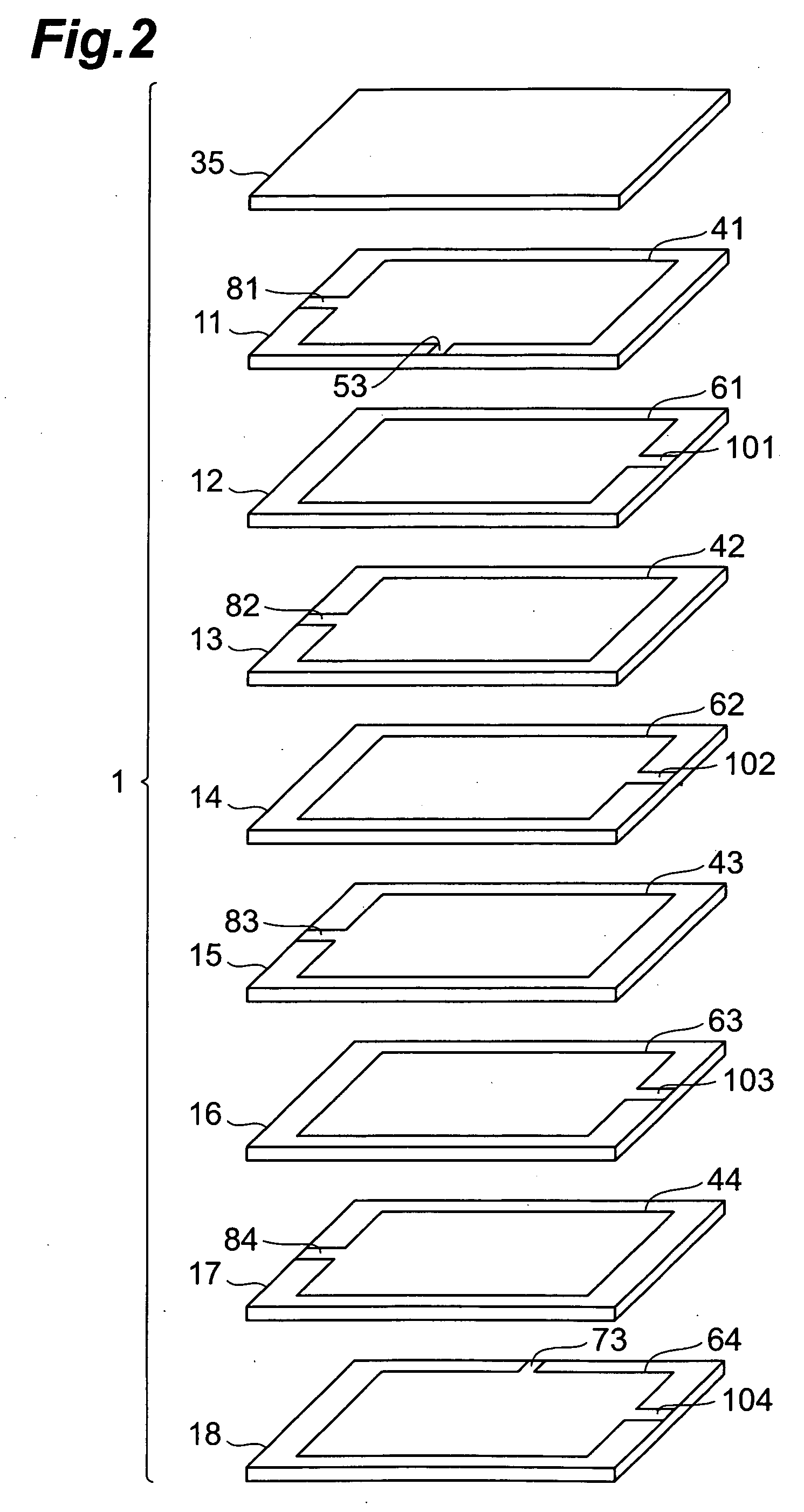
[0190] With reference to FIG. 11, the structure of the multilayer capacitor in accordance with a tenth embodiment will be explained. The multilayer capacitor in accordance with the tenth embodiment differs from the multilayer capacitor C1 in accordance with the first embodiment in that first and second inner electrodes 42 to 44, 61 to 63 are formed with slits. FIG. 11 is an exploded perspective view of the multilayer body included in the multilayer capacitor in accordance with the tenth embodiment.

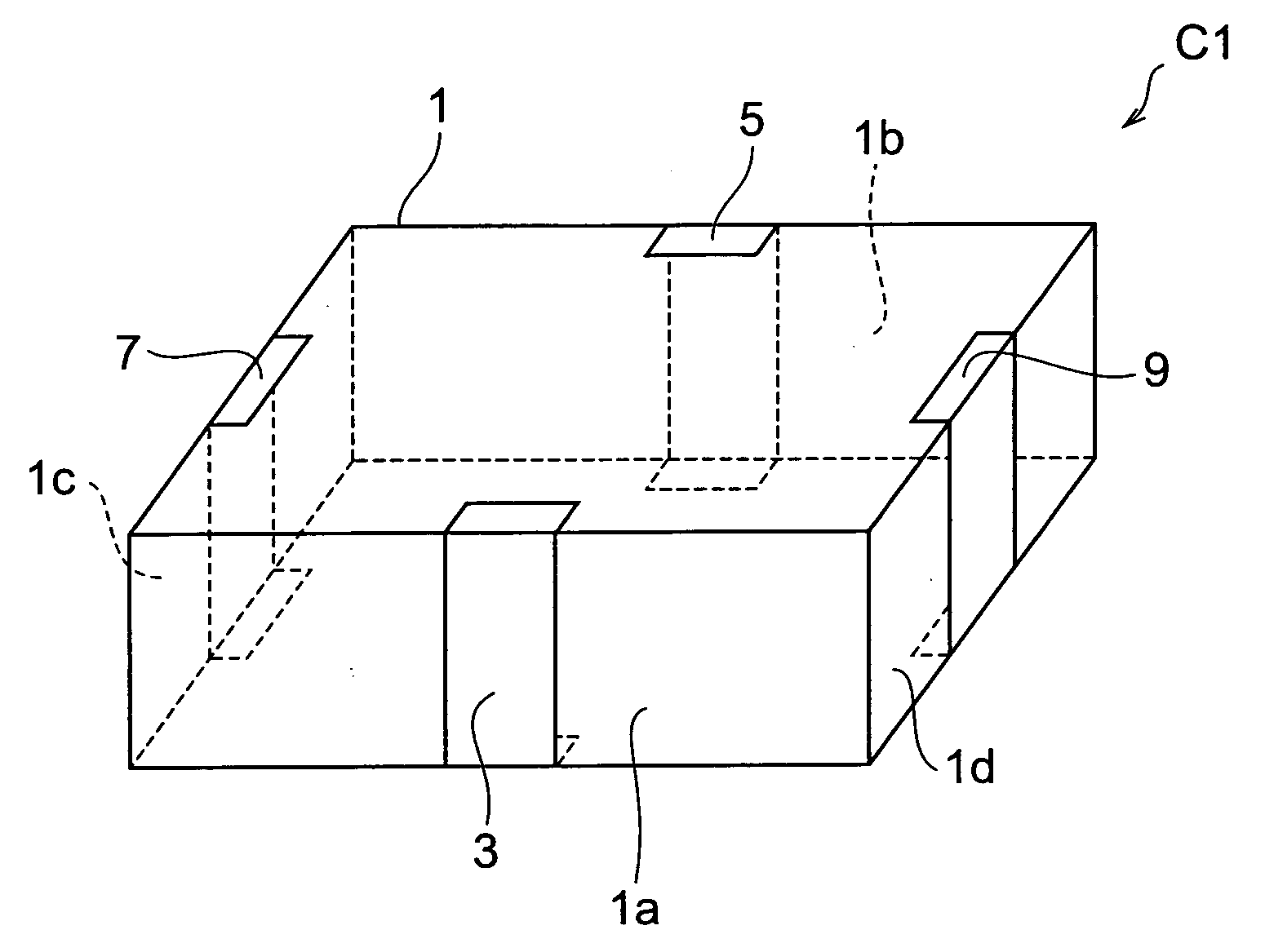
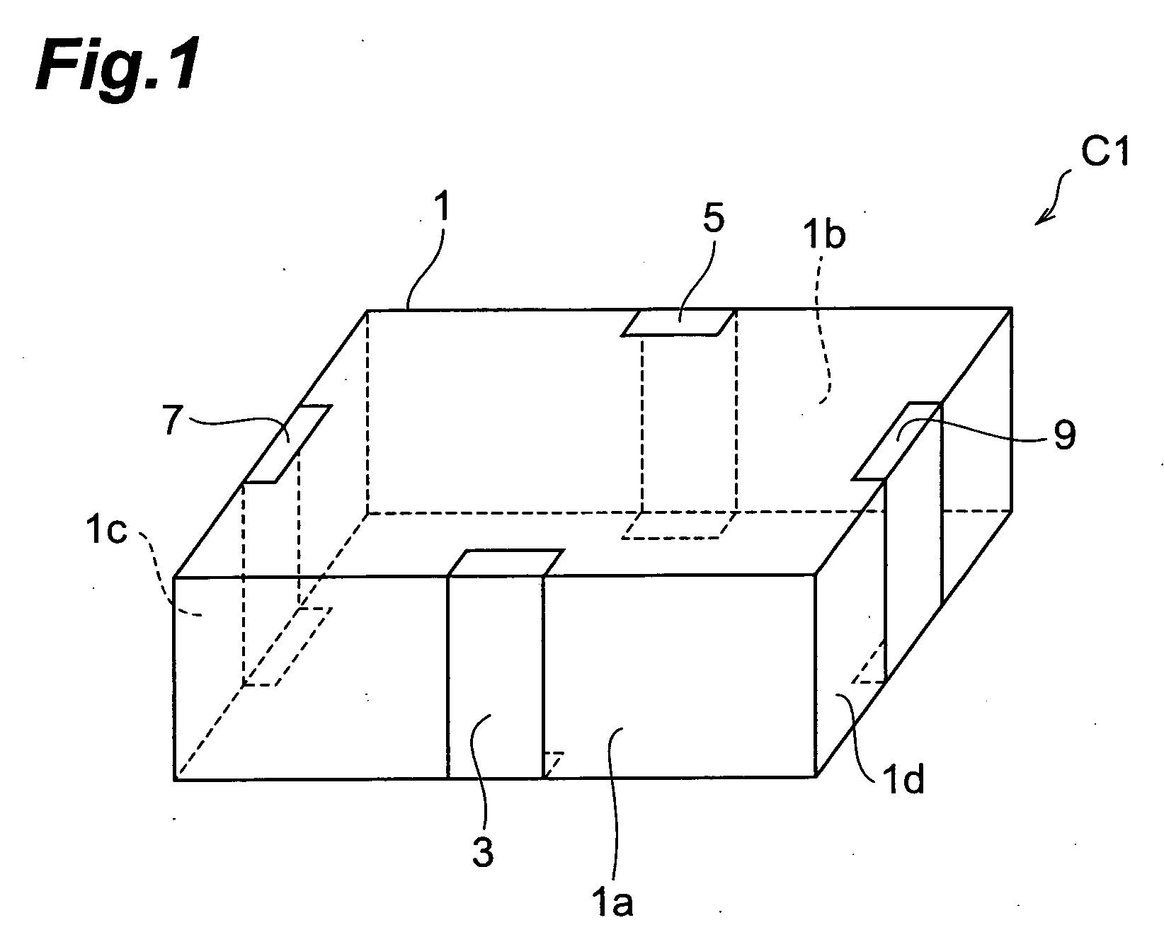
[0191] As with the multilayer capacitor C1 in accordance with the first embodiment, the multilayer capacitor in accordance with the tenth embodiment comprises a multilayer body 1, a first terminal electrode 3 formed on the multilayer body 1, a second terminal electrode 5 similarly formed on the multilayer body 1, and first and second connecting conductors 7, 9, which are not depicted.

[0192] The first inner electrodes 42 to 44 are formed with slits S11 to S13 extending in the longitudinal...

eleventh embodiment

[0197] With reference to FIG. 12, the structure of the multilayer capacitor in accordance with an eleventh embodiment will be explained. FIG. 12 is an exploded perspective view of the multilayer body included in the multilayer capacitor in accordance with the eleventh embodiment.

[0198] As with the multilayer capacitor C1 in accordance with the first embodiment, the multilayer capacitor in accordance with the eleventh embodiment comprises a multilayer body 1, a first terminal electrode 3 formed on the multilayer body 1, a second terminal electrode 5 similarly formed on the multilayer body 1, and first and second connecting conductors 7, 9, which are not depicted.

[0199] As shown in FIG. 12, the multilayer body 1 includes first to third capacitor portions 121, 131, 141. The first capacitor portion 121 is positioned between the second capacitor portion 131 and third capacitor portion 141.

[0200] To begin with, the structure of the first capacitor portion 121 will be explained. The fir...

twelfth embodiment

[0205] With reference to FIG. 13, the structure of the multilayer capacitor in accordance with a twelfth embodiment will be explained. The multilayer capacitor in accordance with the twelfth embodiment differs from the multilayer capacitor in accordance with the eleventh embodiment in terms of the structure of the first capacitor portion 121. FIG. 13 is an exploded perspective view of the multilayer body included in the multilayer capacitor in accordance with the twelfth embodiment.

[0206] As with the multilayer capacitor C1 in accordance with the first embodiment, the multilayer capacitor in accordance with the twelfth embodiment comprises a multilayer body 1, a first terminal electrode 3 formed on the multilayer body 1, a second terminal electrode 5 similarly formed on the multilayer body 1, and first and second connecting conductors 7, 9, which are not depicted.

[0207] The first capacitor portion 121 has the same configuration as that of the multilayer body 1 in the multilayer ca...


PUM


Abstract

A multilayer capacitor comprises a multilayer body in which a plurality of dielectric layers and a plurality of inner electrodes are alternately laminated, and first and second terminal conductors and a plurality of connecting conductors formed on side faces of the multilayer body. The plurality of first inner electrodes are electrically connected to each other through the connecting conductors. In the plurality of first inner electrodes, at least one first inner electrode whose number is smaller than the total number of first inner electrodes by at least 1 is electrically connected to the first terminal conductor through a lead conductor. The plurality of second inner electrodes are electrically connected to each other through the connecting conductors. In the plurality of second inner electrodes, at least one second inner electrode whose number is smaller than the total number of second inner electrodes by at least 1 is electrically connected to the second terminal conductor through a lead conductor. The equivalent series resistance of the multilayer capacitor is set to a desirable value by adjusting the number or position of at least one species of the first inner electrodes electrically connected to the first terminal conductor through the lead conductor and the second inner electrodes electrically connected to the second terminal conductor through the lead conductor.

Description

BACKGROUND OF THE INVENTION [0001] 1. Field of the Invention [0002] The present invention relates to a multilayer capacitor. [0003] 2. Related Background Art [0004] Known as this kind of multilayer capacitor is one comprising a multilayer body in which a plurality of dielectric layers and a plurality of inner electrodes are alternately laminated, and a plurality of terminal conductors formed on the multilayer body. [0005] Power supplies for central processing units (CPUs) mounted in digital electronic devices have been increasing their load current while lowering their voltage. Therefore, it has become very difficult to suppress the fluctuation in power supply voltage under a tolerable level in response to a drastic change in load current, whereby a multilayer capacitor known as decoupling capacitor has come into connection with a power supply. At the time when the load current fluctuates transiently, the multilayer capacitor supplies a current to the CPU, thereby suppressing the fl...

Claims


Application Information

Patent Timeline
IPC IPC(8): H01G4/005
CPCH01G4/005H01G4/30A63B33/00A63B2208/03A63B2209/00
Inventor TOGASHI, MASAAKI
Owner TDK CORPARATION
Why Eureka
Try Eureka